ASSEMBLY
ASSEMBLY
DEALER SETUP INSTRUCTIONS
Set up mower as received from factory with these instructions.
This mower is shipped partially assembled. Assembly will be easier if components are aligned and loosely assembled before tightening hardware. Refer to bolt torque chart in Maintenance Section. All bolts are Grade 5 unless otherwise specified.
All references to location as right, left, front, rear, top and bottom is viewed facing the direction of forward travel when the implement is properly attached to the operating power unit.
Never work under the Implement, the framework, or any lifted component unless the Implement is securely supported or blocked up to prevent sudden or inadvertent falling which could cause serious injury or even death.
Do not modify or alter this Implement. Do not permit anyone to modify or alter this Implement, any of its components or any Implement function.
HITCH LINKAGE SETUP INSTRUCTIONS
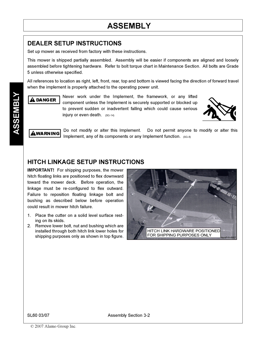
IMPORTANT! For shipping purposes, the mower hitch floating links are positioned to flex downward toward the mower deck. Before operation, the linkage must be
1.Place the cutter on a solid level surface rest- ing on its skids.
2.Remove lower bolt, nut and bushing which are installed through both hitch link lower holes for shipping purposes only as shown in top figure.
SL60 03/07 | Assembly Section |
© 2007 Alamo Group Inc.