Manuals
/
Brands
/
Laundry Appliance
/
Washer
/
Alliance Laundry Systems
/
Laundry Appliance
/
Washer
Alliance Laundry Systems
PHM798N, PHM802N manual
1
1
61
61
Download
61 pages, 2.61 Mb
Installation
www.comlaundry.com
W
asher-Extractors
Pocket Hardmount
UniLinc and M30 Control
Refer to Page 8 for Model Numbers
PHM798N
PHM802N
PHM798N
PHM802N
M30 35 – 125 Models
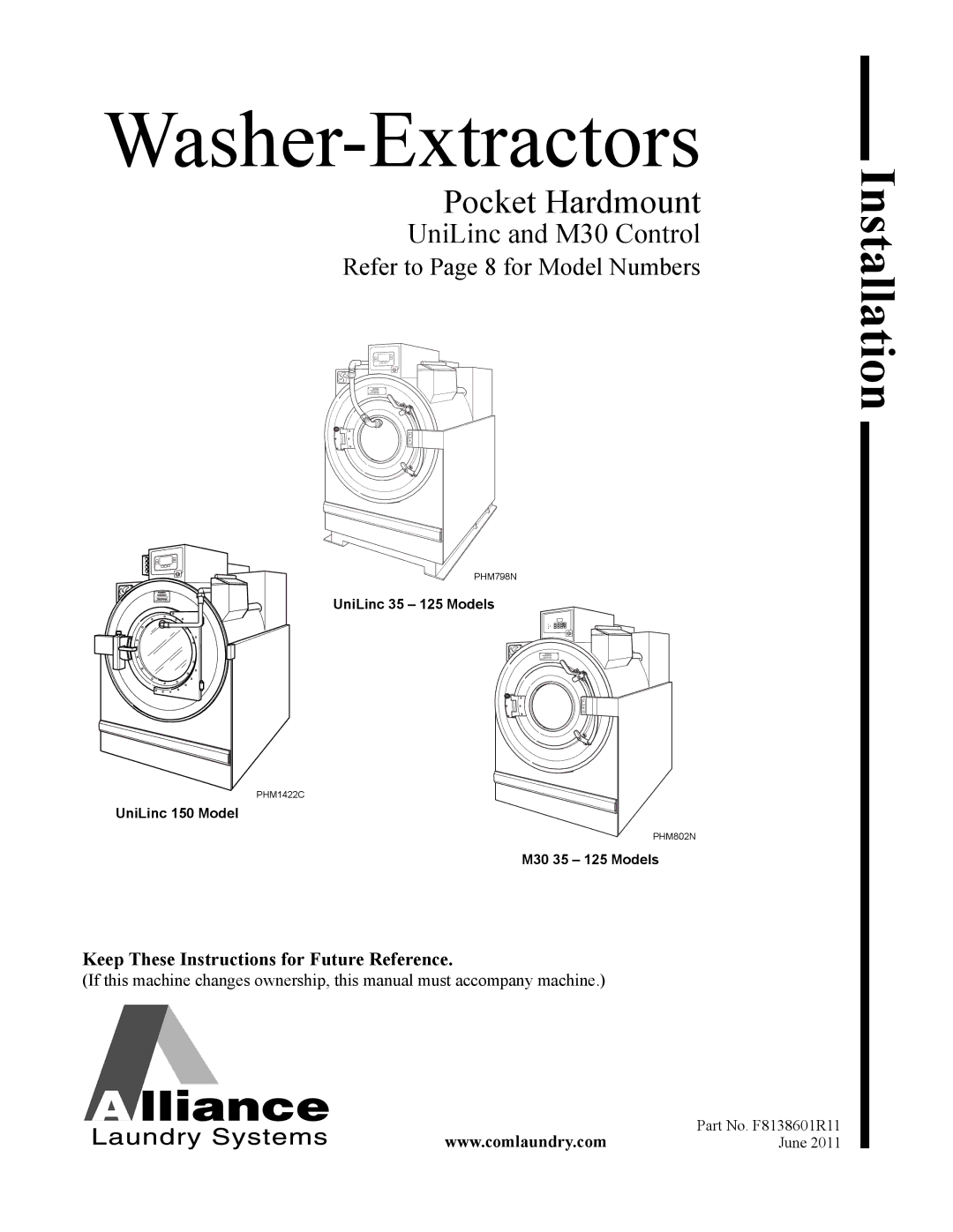
UniLinc 35 – 125 Models
PHM1422C
PHM1422C
UniLinc 150 Model
Part No. F8138601R11
June 2011
Keep These Instructions for Future Reference.
(If this machine changes ownership, th
is manual must accompany machine.)
Contents
Main
Installation
www.comlaundry.com
Washer-Extractors
(If this machine changes ownership, this manual must accompany machine.)
Pocket Hardmount
UniLinc and M30 Control
Refer to Page 8 for Model Numbers
Page
Table of Contents
Safety Information
Explanation of Safety Messages
Important Safety Instructions
DANGER
Page
Safety Decals
Operator Safety
Safe Operating Environment
Environmental Conditions
Machine Location
DANGER
Input and Output Services
AC Inverter Drive
Introduction
Model Identification
Information in this manual is applicable to these models:
Delivery Inspection
Name plate Location
Nameplate Location - UniLinc Models
Replacement Parts
Customer Service
Page
Specifications and Dimensions
UWTV Models Through 3/31/09
* Basket Only
Overall Dimensions
Weight And Shipping Information
12
UWTV Models Through 3/31/09 (Continued)
Cylinder Speeds / Centrifugal Force Data
Balance Detection
Direct Steam Heating (Optional)
13
UWL, UWN and UWU Models Starting 4/1/09 Specifications 35 60 80 100 125 150 Overall Dimensions
* Basket Only
Weight And Shipping Information
Wash Cylinder Information
14
UWL, UWN and UWU Models Starting 4/1/09 (Continued)
Cylinder Speeds / Centrifugal Force Data
Balance Detection
Direct Steam Heating (Optional)
Machine Dimensions
Dimensional Clearances
UWTV Models Through 3/31/09
Crush hazard.
(Refer to Figure 3 and Figure 4)
16
Figure 3
17
Figure 4
UW Design 1 and Design 2 Models Starting 4/1/09 Through 10/3/10 (Refer to Figure 5 and Figure 6)
19
Figure 5
20
Figure 6
UW Design 3 Models starting 10/4/10 (Refer to Figure 7 and Figure 8)
22
Figure 7
23
Figure 8
Machine Foundation Requirements
Concrete Foundation Pad Installation
Page
Floor Load Data
Static and dynamic loads on the floor or foundation are shown in Tabl e 4 and Table 5.
Page
Page
Mounting Bolt Installation Requirements
Machine Mounting and Grouting
32
Mounting Bolt Hole Locations
AA
Figure 12
NOTE: Mounting holes marked A are on V-speed Models only.
35 MODEL
33
Figure 13
60 VARIABLE-SPEED MODEL
34
Figure 14
80 / 100 MODELS
35
Figure 15
125 MODEL
F8138601
36
Figure 16
150 MODEL
37
Grout Placement
125 MODEL
60 2-SPEED MODEL
100 MODEL
80 MODEL
Gap Setting for Vibration Switch
For UniLinc Models, Navigate to the Inputs Outputs Menu:
Verify Vibration Switch Gap (for 35-125 Pound Models):
Verify Vibration Switch Gap (For 150 Pound Design 1 Models):
Verify Safety Switch Operation (For 150 Pound Design 2 Models):
35 Pound Model
60, 80, 100 and 125 Pound Models
Page
Drain Connection Requirements
Page
Water Connection
Page
Electrical Installation Requirements
Page
Page
Page
** M30 Control Models only.
Steam Requirements (Steam Heat Option Only)
Chemical Injection Supply System Undiluted chemical dripping can damage the washer-
Connecting External Liquid Supplies to the Washer-Extractor
IMPORTANT: Do not attach anything to nozzles. Air gap must be maintained.
External Supplies
Chemical Injection Using Internal 24VAC Control Transformer
Chemical injection Using External AC Power Source
External Supply Signals