1
2
3
![]() 4
4
5
6
PHM559N
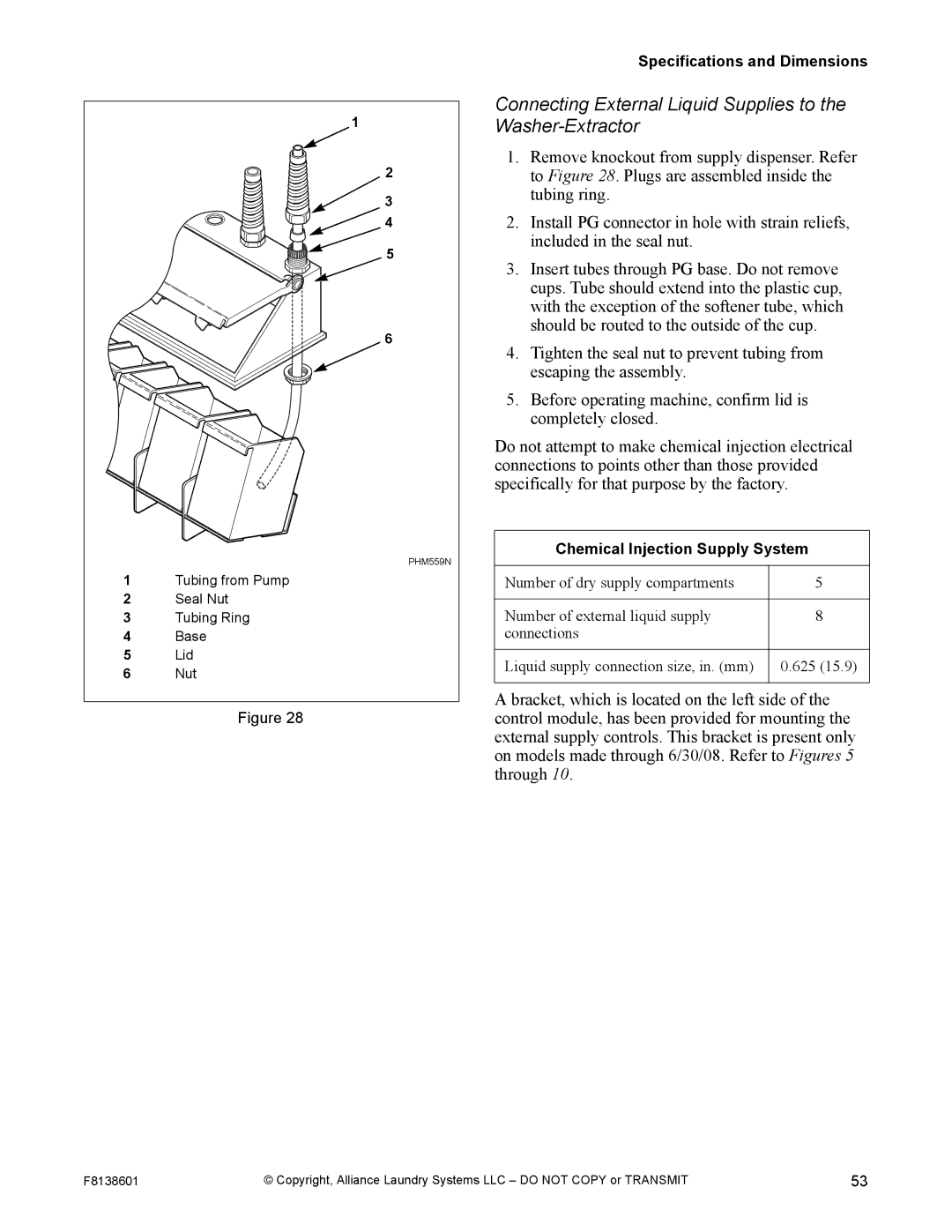
1Tubing from Pump
2Seal Nut
3Tubing Ring
4Base
5Lid
6Nut
Figure 28
Specifications and Dimensions
Connecting External Liquid Supplies to the Washer-Extractor
1.Remove knockout from supply dispenser. Refer to Figure 28. Plugs are assembled inside the tubing ring.
2.Install PG connector in hole with strain reliefs, included in the seal nut.
3.Insert tubes through PG base. Do not remove cups. Tube should extend into the plastic cup, with the exception of the softener tube, which should be routed to the outside of the cup.
4.Tighten the seal nut to prevent tubing from escaping the assembly.
5.Before operating machine, confirm lid is completely closed.
Do not attempt to make chemical injection electrical connections to points other than those provided specifically for that purpose by the factory.
Chemical Injection Supply System
Number of dry supply compartments | 5 |
|
|
Number of external liquid supply | 8 |
connections |
|
|
|
Liquid supply connection size, in. (mm) | 0.625 (15.9) |
|
|
A bracket, which is located on the left side of the control module, has been provided for mounting the external supply controls. This bracket is present only on models made through 6/30/08. Refer to Figures 5 through 10.
F8138601 | © Copyright, Alliance Laundry Systems LLC – DO NOT COPY or TRANSMIT | 53 |