On
Specifications and Dimensions
WARNING
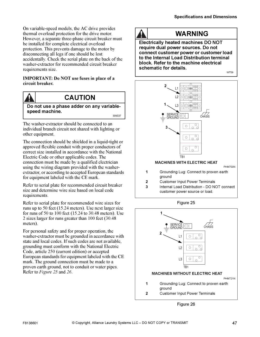
Electrically heated machines DO NOT require dual power sources. Do not connect customer power or customer load to the Internal Load Distribution terminal block. Refer to the machine electrical schematic for details.
IMPORTANT: Do NOT use fuses in place of a circuit breaker.
CAUTION
2
W759
L1
L2 ![]()
![]()
![]()
![]()
![]()
![]()
![]()
Do not use a phase adder on any variable- speed machine.
SW037
The
The connection should be shielded in a
Refer to serial plate for recommended circuit breaker size and determine wire size based on local code requirements.
Refer to serial plate for recommended wire sizes for runs up to 50 feet (15.24 meters). Use next larger size for runs of 50 to 100 feet (15.24 to 30.48 meters). Use 2 sizes larger for runs greater than 100 feet (30.48 meters).
For personal safety and for proper operation, the
1L3 ![]()
![]()
![]()
![]()
![]()
![]()
![]()
![]()
![]()
SERVICE | CHASIS |
GROUND |
3
TB1
MACHINES WITH ELECTRIC HEAT | PHM |
| |
| PHM700N |
1Grounding Lug: Connect to proven earth ground
2Customer Input Power Terminals
3Internal Load Distribution - DO NOT connect customer power source or load.
Figure 25
1
SERVICE | CHASIS |
GROUND |
2
![]() L1
L1
L2
L3
TB1
MACHINES WITHOUT ELECTRIC HEAT | P |
| |
| PHM721N |
1Grounding Lug: Connect to proven earth ground
2Customer Input Power Terminals
Figure 26
F8138601 | © Copyright, Alliance Laundry Systems LLC – DO NOT COPY or TRANSMIT | 47 |