Chapter 1: Overview
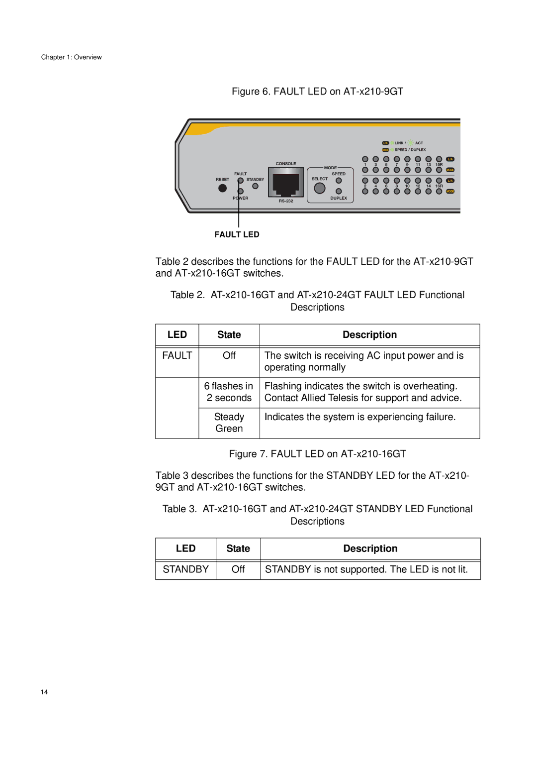
Figure 6. FAULT LED on AT-x210-9GT
CONSOLE
FAULT
RESET ![]() STANDBY
STANDBY
POWER ![]()
L/A ![]() LINK /
LINK / ![]()
![]() ACT
ACT
MODE ![]() SPEED / DUPLEX
SPEED / DUPLEX
L/A
1 3 5 7 9 11 13 15R
MODE
MODE
SPEED
SELECT | L/A |
2 4 6 8 10 12 14 16R
MODE
DUPLEX
FAULT LED
Table 2 describes the functions for the FAULT LED for the
Table 2.
Descriptions
LED | State | Description |
|
|
|
|
|
|
FAULT | Off | The switch is receiving AC input power and is |
|
| operating normally |
|
|
|
| 6 flashes in | Flashing indicates the switch is overheating. |
| 2 seconds | Contact Allied Telesis for support and advice. |
|
|
|
| Steady | Indicates the system is experiencing failure. |
| Green |
|
|
|
|
| Figure 7. FAULT LED on | |
Table 3 describes the functions for the STANDBY LED for the
Table 3.
Descriptions
LED | State | Description |
|
|
|
|
|
|
STANDBY | Off | STANDBY is not supported. The LED is not lit. |
|
|
|
14