Powering On the Switch
To power on the
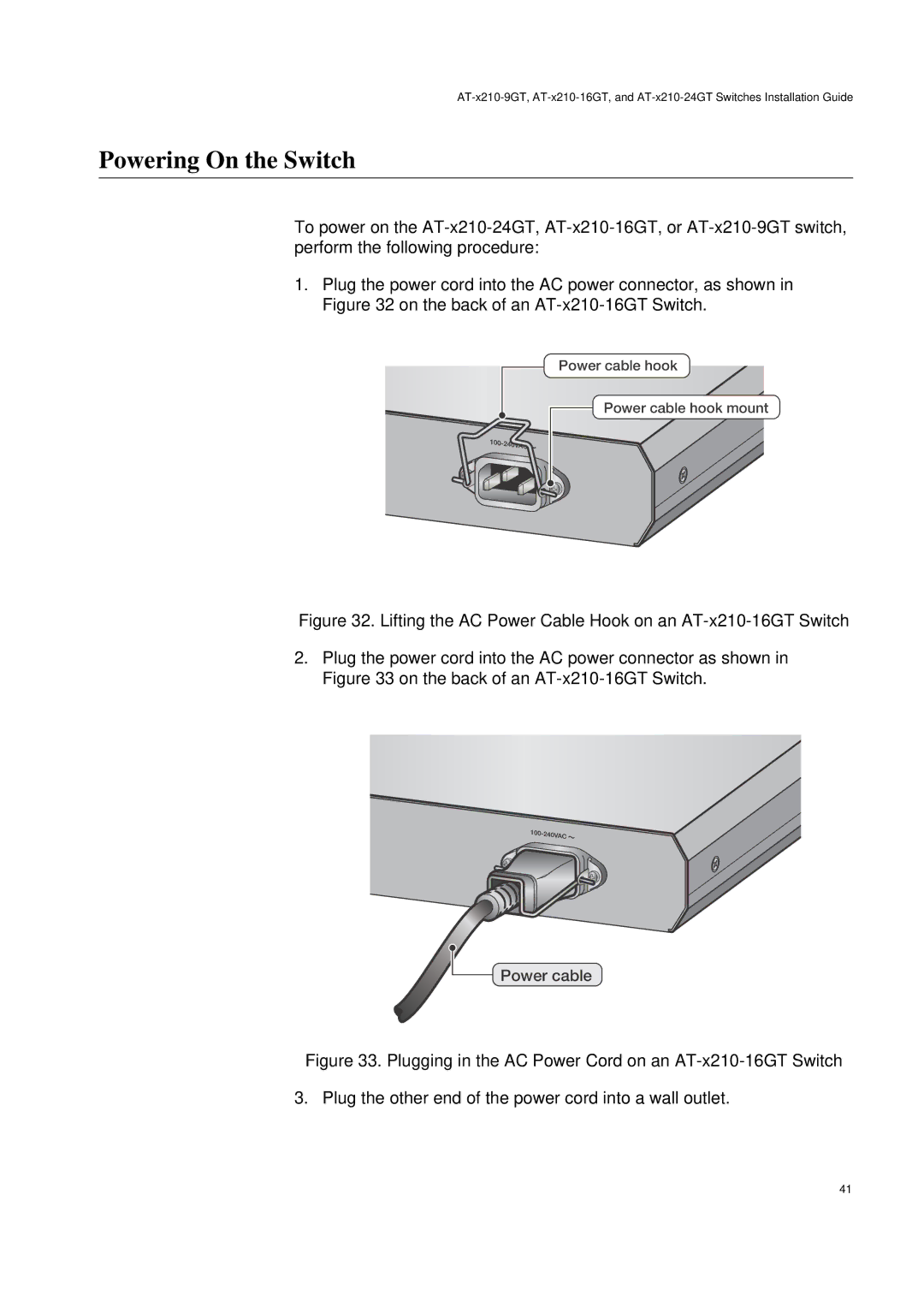
1.Plug the power cord into the AC power connector, as shown in Figure 32 on the back of an
Power cable hook
Power cable hook mount
Figure 32. Lifting the AC Power Cable Hook on an AT-x210-16GT Switch
2.Plug the power cord into the AC power connector as shown in Figure 33 on the back of an AT-x210-16GT Switch.
Power cable
Figure 33. Plugging in the AC Power Cord on an AT-x210-16GT Switch
3. Plug the other end of the power cord into a wall outlet.
41