Chapter 2: Installation
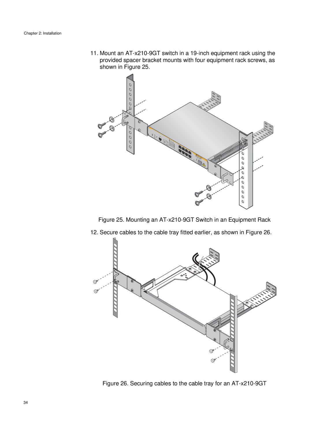
11.Mount an
RESET | FAULT |
| POWER |
STANDBY
CONSOLE |
|
|
|
|
|
|
|
RS- | MODE |
| INK/ |
|
| ||
| SELECT |
|
| L |
|
|
|
232 | SPEED |
| SP | EED/ | ACT |
| |
|
| 1 |
|
| |||
|
|
|
| 3 | 5 | DUPLEX |
|
|
| DUPLEX | 2 | 4 |
| 7 | L/A |
|
|
|
|
| 6 |
|
|
|
|
|
|
|
| 8 | L/A |
1
3
5
![]()
![]() 7 2
7 2 ![]()
![]()
4
6
8
ATGi - |
|
x210 | |
gabit | - |
Ethernet | |
| Sw9GTitch |
SFP | |
LINK/ |
|
ACT |
|
| 9 |
Figure 25. Mounting an AT-x210-9GT Switch in an Equipment Rack
12. Secure cables to the cable tray fitted earlier, as shown in Figure 26.
Figure 26. Securing cables to the cable tray for an AT-x210-9GT
34