Chapter 2: Installation
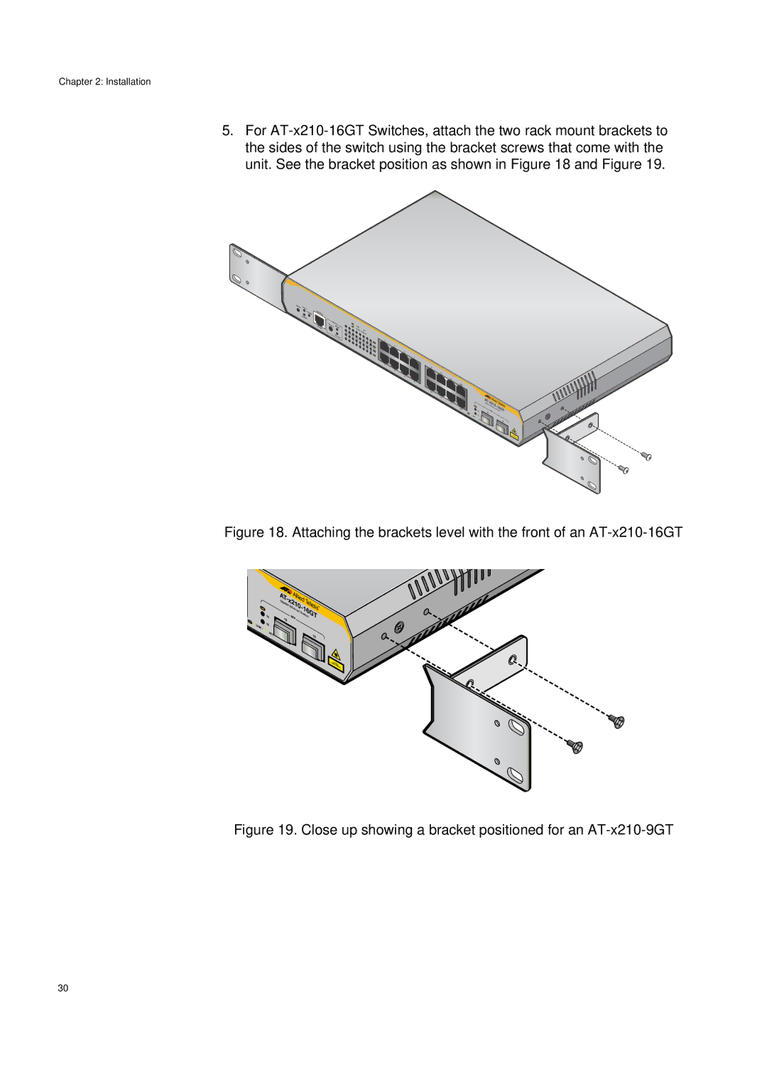
5.For
RESET FAULT
STANDBY
POWER
CONSOLE |
|
|
|
|
|
|
|
|
| MODE |
| L/A |
|
|
|
| |
SELECT | SPEED | 1 | MODE | LINK/ |
|
|
| |
|
|
| 3 |
| SPEED/ | ACT |
|
|
|
| DUPLEX |
| 5 | 7 | DUPLEX |
|
|
|
| 4 |
| 9 | 11 |
|
| |
|
|
| 2 |
|
|
|
| |
|
|
|
| 6 | 8 | 13 | 15R | L/A |
|
|
|
|
|
| |||
|
|
|
|
| 10 | 12 |
| MODE |
|
|
|
|
|
|
| ||
|
|
|
|
|
| 14 | 16R | L/A |
|
|
|
|
|
|
| ||
|
|
|
|
|
|
|
| MODE |
1
3
5
7
2 9
4 11
6 13
8 15R
10
12 |
|
| ATGi - |
| |
|
|
|
| ||
14 |
|
|
| x210- | |
|
| gabit |
| ||
16R |
| 15 |
| Ethernet | 16GTtch |
|
| SFP | |||
|
|
|
| Swi | |
| L/A | 16 | 15 |
|
|
|
| LINK/ |
|
|
|
|
| ACT |
|
| 16 |
LASERCLASS
PRODUCT1
Figure 18. Attaching the brackets level with the front of an AT-x210-16GT
L/A
![]() 15
15
LINK/![]() 16
16 ![]()
![]() ACT
ACT
AT |
|
|
|
| |
Gi | - |
|
|
| |
|
| x210 |
| ||
gabit |
| - | |||
|
| Ether |
| ||
|
|
| net |
| 16GTtch |
|
| SFP |
| Swi | |
| 15 |
|
|
| |
|
|
|
|
| |
|
|
|
|
| 16 |
LASERCLASS
PRODUCT1
Figure 19. Close up showing a bracket positioned for an AT-x210-9GT
30
