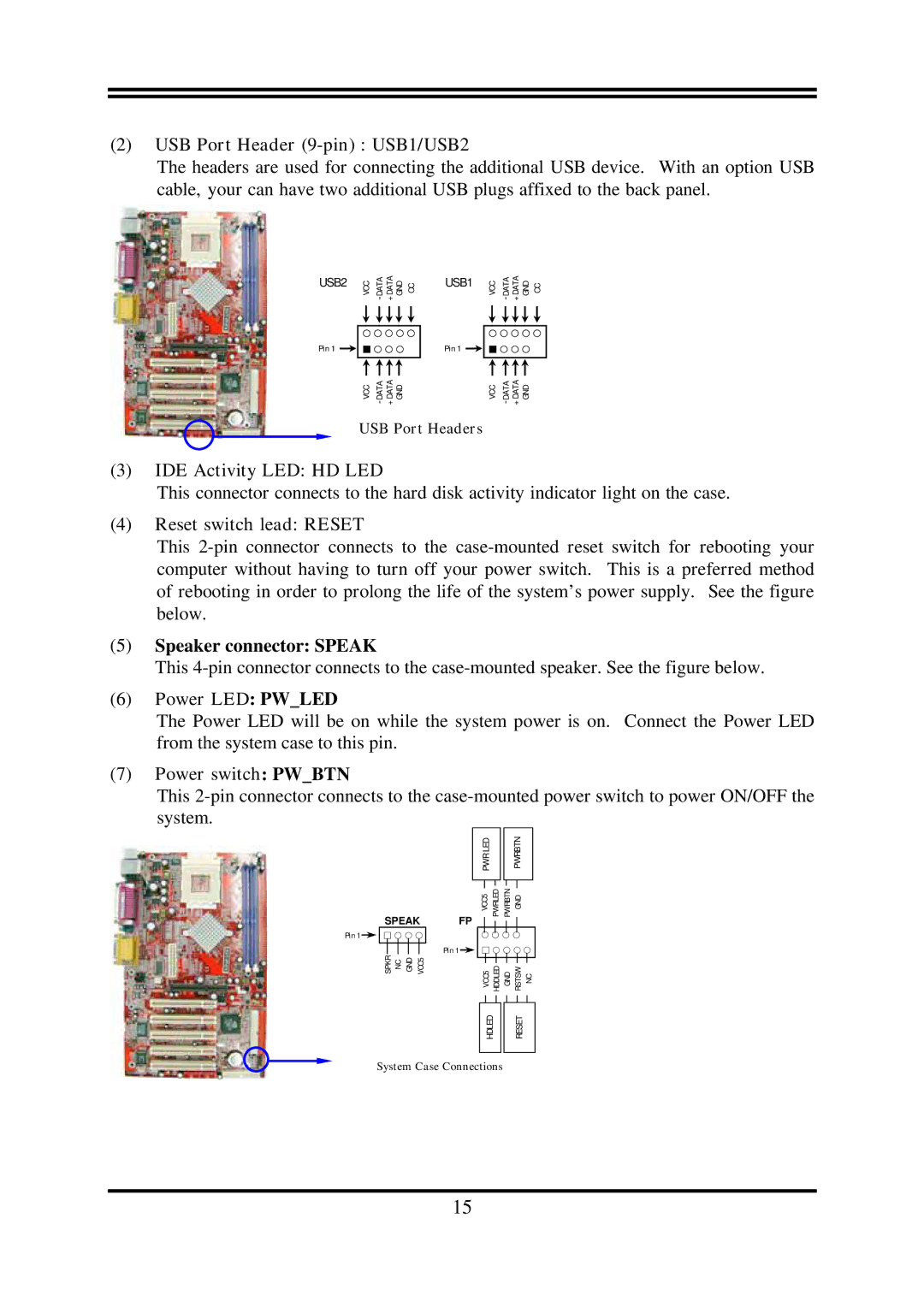
(2)USB Port Header (9-pin) : USB1/USB2
The headers are used for connecting the additional USB device. With an option USB cable, your can have two additional USB plugs affixed to the back panel.
USB2
Pin 1
VCC | OC | USB1 | VCC | OC | ||
| ||||||
|
|
| Pin 1 |
|
|
|
VCC |
|
| VCC |
|
USB Port Headers
(3)IDE Activity LED: HD LED
This connector connects to the hard disk activity indicator light on the case.
(4)Reset switch lead: RESET
This
(5)Speaker connector: SPEAK
This
(6)Power LED: PW_LED
The Power LED will be on while the system power is on. Connect the Power LED from the system case to this pin.
(7)Power switch: PW_BTN
This
SPEAK FP
Pin 1![]()
![]()
Pin 1 ![]()
VCC5
GND
NC
SPKR
PWR LED |
|
| PWRBTN |
VCC5 | PWRLED | PWRBTN | GND |
VCC5 | HDDLED | GND | RSTSW NC |
HDLED
System Case Connections
RESET
15
