Chapter 1 | Setting Up the CoreModule 800 |
J4
Flat Panel | D9 D10 |
| |
Voltage |
|
Select (JP4) | JP4 |
|
U1
J1
![]() J3
J3 ![]() U11
U11
J8
J5
JP3
D17 ![]()
U2
J9
Q4
Serial 1
J7 | J6 | JP1 | JP2 |
|
CMOS Normal/ | Serial 2 |
Clear (JP1) | Termination (JP2) |
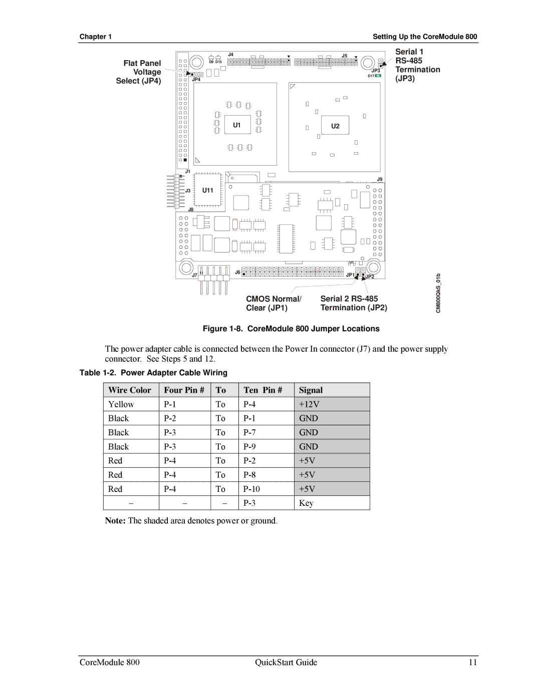
Figure 1-8. CoreModule 800 Jumper Locations
CM800QkS_01b
The power adapter cable is connected between the Power In connector (J7) and the power supply connector. See Steps 5 and 12.
Table
Wire Color | Four Pin # | To | Ten Pin # | Signal |
Yellow | To | +12V | ||
Black | To | GND | ||
Black | To | GND | ||
Black | To | GND | ||
Red | To | +5V | ||
Red | To | +5V | ||
Red | To | +5V | ||
– | – | – | Key | |
|
|
|
|
|
Note: The shaded area denotes power or ground.
CoreModule 800 | QuickStart Guide | 11 |