Appendix B |
|
|
|
|
| I/O Interface Board | |||
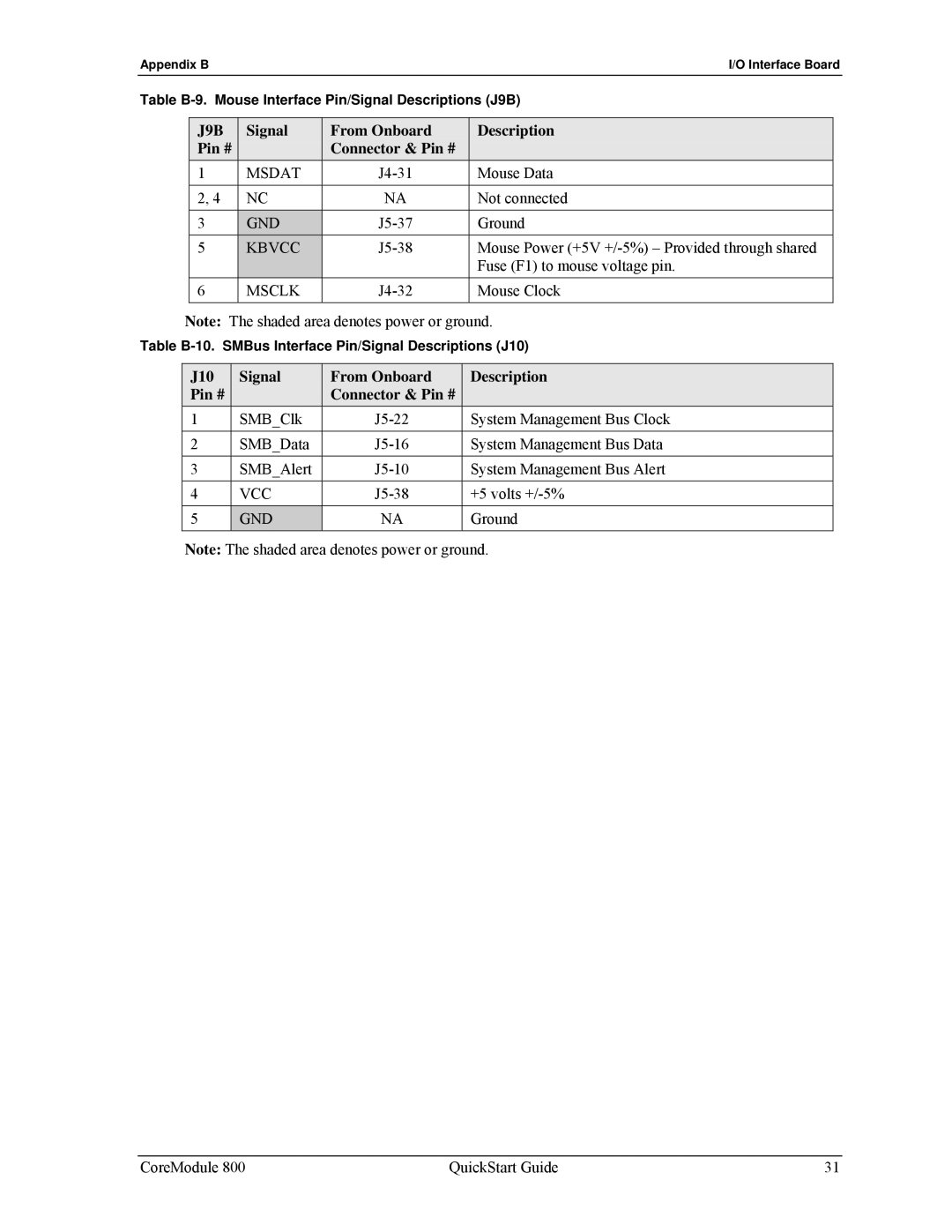
Table | Mouse Interface Pin/Signal Descriptions (J9B) | ||||||||
|
|
|
|
|
|
|
|
| |
|
| J9B | Signal | From Onboard | Description |
| |||
|
| Pin # |
| Connector & Pin # |
|
| |||
|
| 1 |
|
| MSDAT | Mouse Data |
| ||
|
| 2, 4 |
| NC | NA | Not connected |
| ||
|
|
|
|
|
|
|
|
|
|
|
| 3 |
|
| GND | Ground |
| ||
|
| 5 |
|
| KBVCC | Mouse Power (+5V |
| ||
|
|
|
|
|
|
|
| Fuse (F1) to mouse voltage pin. |
|
|
| 6 |
|
| MSCLK | Mouse Clock |
| ||
|
|
|
|
|
|
|
|
| |
| Note: The shaded area denotes power or ground. | ||||||||
Table | SMBus Interface Pin/Signal Descriptions (J10) | ||||||||
|
|
|
|
|
|
|
|
| |
|
| J10 |
|
| Signal | From Onboard |
| Description |
|
|
| Pin # |
|
| Connector & Pin # |
|
|
| |
| 1 |
|
| SMB_Clk |
| System Management Bus Clock |
| ||
| 2 |
|
| SMB_Data |
| System Management Bus Data |
| ||
|
|
|
|
|
|
|
|
| |
| 3 |
|
| SMB_Alert |
| System Management Bus Alert |
| ||
|
|
|
|
|
|
|
|
| |
| 4 |
|
| VCC |
| +5 volts |
| ||
| 5 |
|
| GND | NA |
| Ground |
| |
|
|
|
|
|
|
|
|
|
|
Note: The shaded area denotes power or ground.
CoreModule 800 | QuickStart Guide | 31 |