Appendix B |
|
| I/O Interface Board | |
Table | ||||
|
|
|
|
|
| Pin # | Signal | Description | |
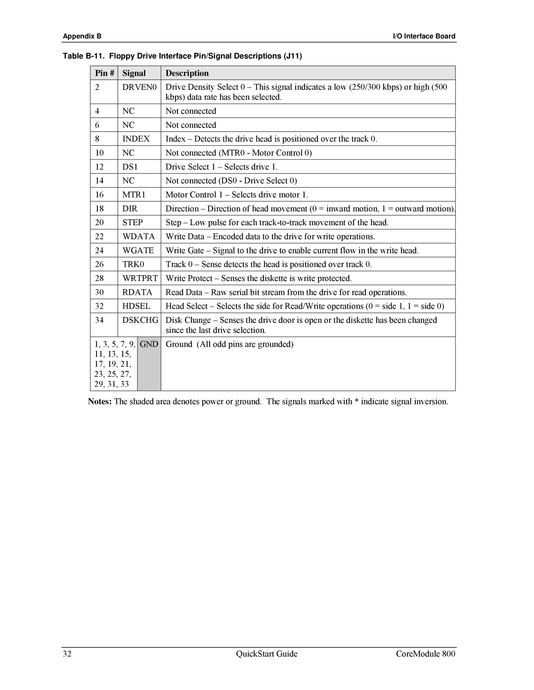
| 2 | DRVEN0 | Drive Density Select 0 – This signal indicates a low (250/300 kbps) or high (500 | |
|
|
|
| kbps) data rate has been selected. |
| 4 | NC | Not connected | |
|
|
|
|
|
| 6 | NC | Not connected | |
|
|
|
|
|
| 8 | INDEX | Index – Detects the drive head is positioned over the track 0. | |
| 10 | NC | Not connected (MTR0 - Motor Control 0) | |
|
|
|
|
|
| 12 | DS1 | Drive Select 1 – Selects drive 1. | |
|
|
|
|
|
| 14 | NC | Not connected (DS0 - Drive Select 0) | |
| 16 | MTR1 | Motor Control 1 – Selects drive motor 1. | |
|
|
|
|
|
| 18 | DIR | Direction – Direction of head movement (0 = inward motion, 1 = outward motion). | |
|
|
|
|
|
| 20 | STEP | Step – Low pulse for each | |
| 22 | WDATA | Write Data – Encoded data to the drive for write operations. | |
|
|
|
|
|
| 24 | WGATE | Write Gate – Signal to the drive to enable current flow in the write head. | |
|
|
|
|
|
| 26 | TRK0 | Track 0 – Sense detects the head is positioned over track 0. | |
| 28 | WRTPRT | Write Protect – Senses the diskette is write protected. | |
|
|
|
|
|
| 30 | RDATA | Read Data – Raw serial bit stream from the drive for read operations. | |
|
|
|
|
|
| 32 | HDSEL | Head Select – Selects the side for Read/Write operations (0 = side 1, 1 = side 0) | |
| 34 | DSKCHG | Disk Change – Senses the drive door is open or the diskette has been changed | |
|
|
|
| since the last drive selection. |
| 1, 3, 5, 7, 9, | GND | Ground (All odd pins are grounded) | |
| 11, 13, 15, |
|
| |
| 17, 19, 21, |
|
| |
| 23, 25, 27, |
|
| |
| 29, 31, 33 |
|
| |
Notes: The shaded area denotes power or ground. The signals marked with * indicate signal inversion.
32 | QuickStart Guide | CoreModule 800 |
