Appendix B | I/O Interface Board |
Overview
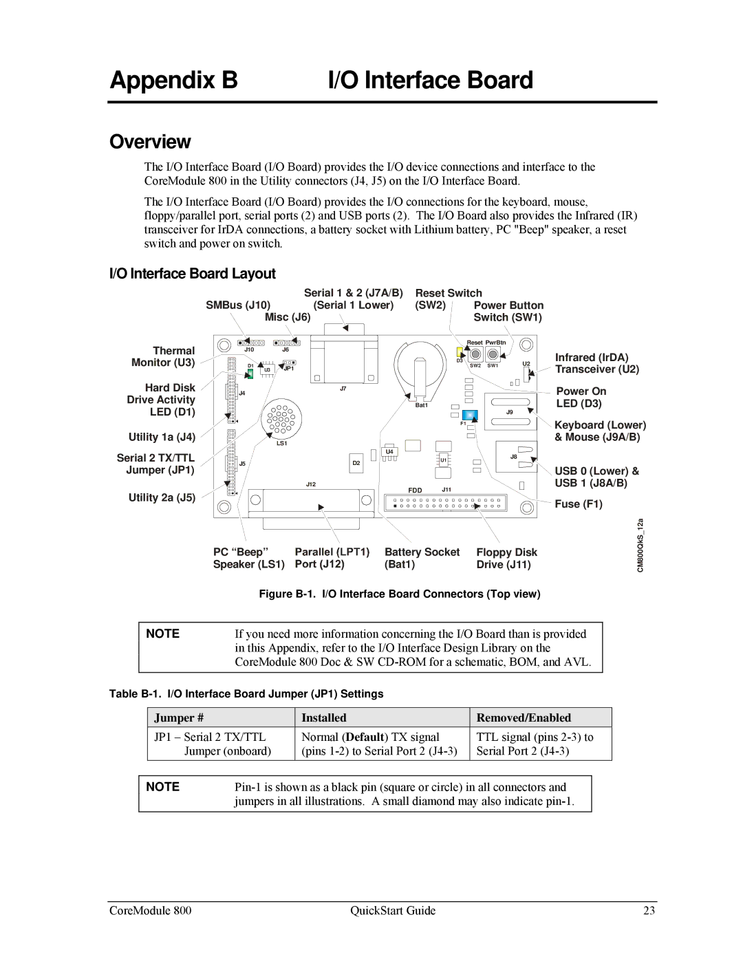
The I/O Interface Board (I/O Board) provides the I/O device connections and interface to the CoreModule 800 in the Utility connectors (J4, J5) on the I/O Interface Board.
The I/O Interface Board (I/O Board) provides the I/O connections for the keyboard, mouse, floppy/parallel port, serial ports (2) and USB ports (2). The I/O Board also provides the Infrared (IR) transceiver for IrDA connections, a battery socket with Lithium battery, PC "Beep" speaker, a reset switch and power on switch.
I/O Interface Board Layout
|
|
| Serial 1 & 2 (J7A/B) | Reset Switch |
|
| ||
| SMBus (J10) |
| (Serial 1 Lower) | (SW2) | Power Button |
| ||
| Misc (J6) |
|
| Switch (SW1) |
| |||
Thermal | J10 | J6 |
|
|
| Reset PwrBtn |
|
|
|
|
|
|
| Infrared (IrDA) | |||
Monitor (U3) |
|
|
|
| D3 |
| U2 | |
D1 | JP1 |
|
|
| SW2 SW1 | Transceiver (U2) | ||
| U3 |
|
|
|
|
| ||
Hard Disk | J4 |
| J7 |
|
|
|
| Power On |
Drive Activity |
|
|
|
|
|
| ||
|
|
| Bat1 |
|
|
| LED (D3) | |
LED (D1) |
|
|
|
|
| J9 | ||
|
|
|
|
|
| Keyboard (Lower) | ||
|
|
|
|
| F1 |
|
| |
Utility 1a (J4) |
|
|
|
|
|
|
| |
| LS1 |
|
|
|
|
| & Mouse (J9A/B) | |
|
|
|
|
|
|
|
| |
Serial 2 TX/TTL |
|
| U4 |
|
|
| J8 |
|
J5 |
| D2 |
| U1 |
|
| ||
|
|
|
| USB 0 (Lower) & | ||||
Jumper (JP1) |
|
|
|
|
|
|
| |
Utility 2a (J5) |
|
| J12 | FDD | J11 |
|
| USB 1 (J8A/B) |
|
|
|
|
|
| |||
|
|
|
|
|
|
| Fuse (F1) | |
|
|
|
|
|
|
|
| |
|
|
|
|
|
|
|
| 12a |
| PC “Beep” |
| Battery Socket | Floppy Disk | CM800QkS | |||
| Speaker (LS1) | (Bat1) |
| Drive (J11) | ||||
Figure B-1. I/O Interface Board Connectors (Top view)
NOTE | If you need more information concerning the I/O Board than is provided |
| in this Appendix, refer to the I/O Interface Design Library on the |
| CoreModule 800 Doc & SW |
|
|
Table
| Jumper # | Installed | Removed/Enabled | ||
| JP1 – Serial 2 TX/TTL | Normal (Default) TX signal | TTL signal (pins | ||
|
| Jumper (onboard) | (pins | Serial Port 2 | |
|
|
| |||
NOTE |
| ||||
|
| jumpers in all illustrations. A small diamond may also indicate |
| ||
|
|
|
|
|
|
CoreModule 800 | QuickStart Guide | 23 |
