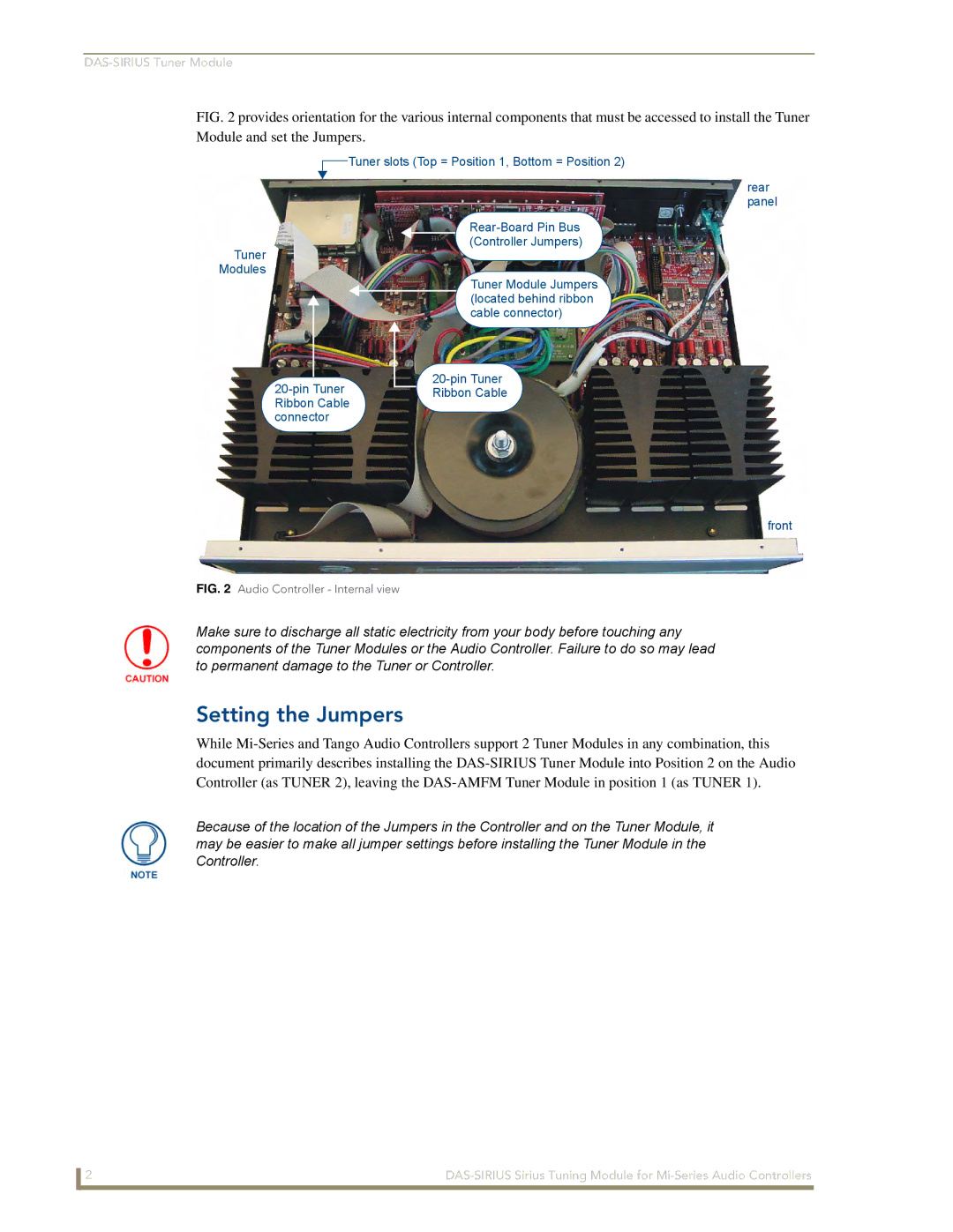
FIG. 2 provides orientation for the various internal components that must be accessed to install the Tuner Module and set the Jumpers.
![]() Tuner slots (Top = Position 1, Bottom = Position 2)
Tuner slots (Top = Position 1, Bottom = Position 2)
Tuner
Modules
rear panel
(Controller Jumpers)
Tuner Module Jumpers (located behind ribbon cable connector)
Ribbon Cable
front
FIG. 2 Audio Controller - Internal view
Make sure to discharge all static electricity from your body before touching any components of the Tuner Modules or the Audio Controller. Failure to do so may lead to permanent damage to the Tuner or Controller.
Setting the Jumpers
While
Because of the location of the Jumpers in the Controller and on the Tuner Module, it may be easier to make all jumper settings before installing the Tuner Module in the Controller.
2 |
