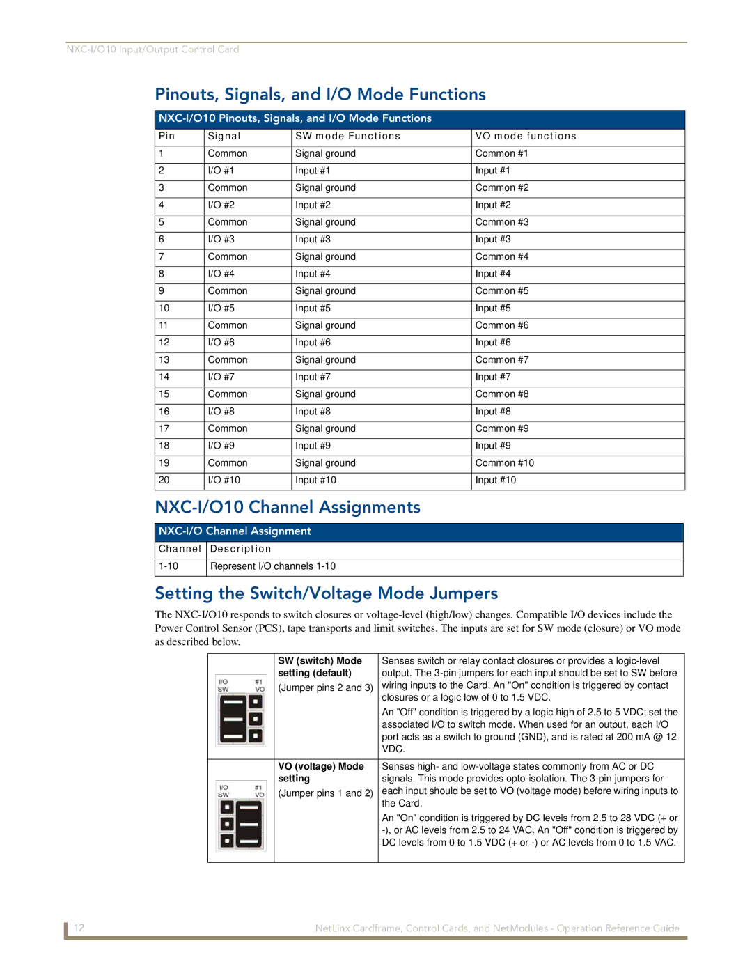
Pinouts, Signals, and I/O Mode Functions
NXC-I/O10 Pinouts, Signals, and I/O Mode Functions
Pin | Signal | SW mode Functions | VO mode functions |
|
|
|
|
1 | Common | Signal ground | Common #1 |
|
|
|
|
2 | I/O #1 | Input #1 | Input #1 |
|
|
|
|
3 | Common | Signal ground | Common #2 |
|
|
|
|
4 | I/O #2 | Input #2 | Input #2 |
|
|
|
|
5 | Common | Signal ground | Common #3 |
|
|
|
|
6 | I/O #3 | Input #3 | Input #3 |
|
|
|
|
7 | Common | Signal ground | Common #4 |
|
|
|
|
8 | I/O #4 | Input #4 | Input #4 |
|
|
|
|
9 | Common | Signal ground | Common #5 |
|
|
|
|
10 | I/O #5 | Input #5 | Input #5 |
|
|
|
|
11 | Common | Signal ground | Common #6 |
|
|
|
|
12 | I/O #6 | Input #6 | Input #6 |
|
|
|
|
13 | Common | Signal ground | Common #7 |
|
|
|
|
14 | I/O #7 | Input #7 | Input #7 |
|
|
|
|
15 | Common | Signal ground | Common #8 |
|
|
|
|
16 | I/O #8 | Input #8 | Input #8 |
|
|
|
|
17 | Common | Signal ground | Common #9 |
|
|
|
|
18 | I/O #9 | Input #9 | Input #9 |
|
|
|
|
19 | Common | Signal ground | Common #10 |
|
|
|
|
20 | I/O #10 | Input #10 | Input #10 |
|
|
|
|
NXC-I/O10 Channel Assignments
NXC-I/O Channel Assignment
Channel Description
Represent I/O channels |
Setting the Switch/Voltage Mode Jumpers
The
| SW (switch) Mode | Senses switch or relay contact closures or provides a |
| setting (default) | output. The |
| (Jumper pins 2 and 3) | wiring inputs to the Card. An "On" condition is triggered by contact |
|
| closures or a logic low of 0 to 1.5 VDC. |
|
| An "Off" condition is triggered by a logic high of 2.5 to 5 VDC; set the |
|
| associated I/O to switch mode. When used for an output, each I/O |
|
| port acts as a switch to ground (GND), and is rated at 200 mA @ 12 |
|
| VDC. |
|
|
|
| VO (voltage) Mode | Senses high- and |
| setting | signals. This mode provides |
| (Jumper pins 1 and 2) | each input should be set to VO (voltage mode) before wiring inputs to |
|
| the Card. |
|
| An "On" condition is triggered by DC levels from 2.5 to 28 VDC (+ or |
|
| |
|
| DC levels from 0 to 1.5 VDC (+ or |
|
|
|
12 | NetLinx Cardframe, Control Cards, and NetModules - Operation Reference Guide |