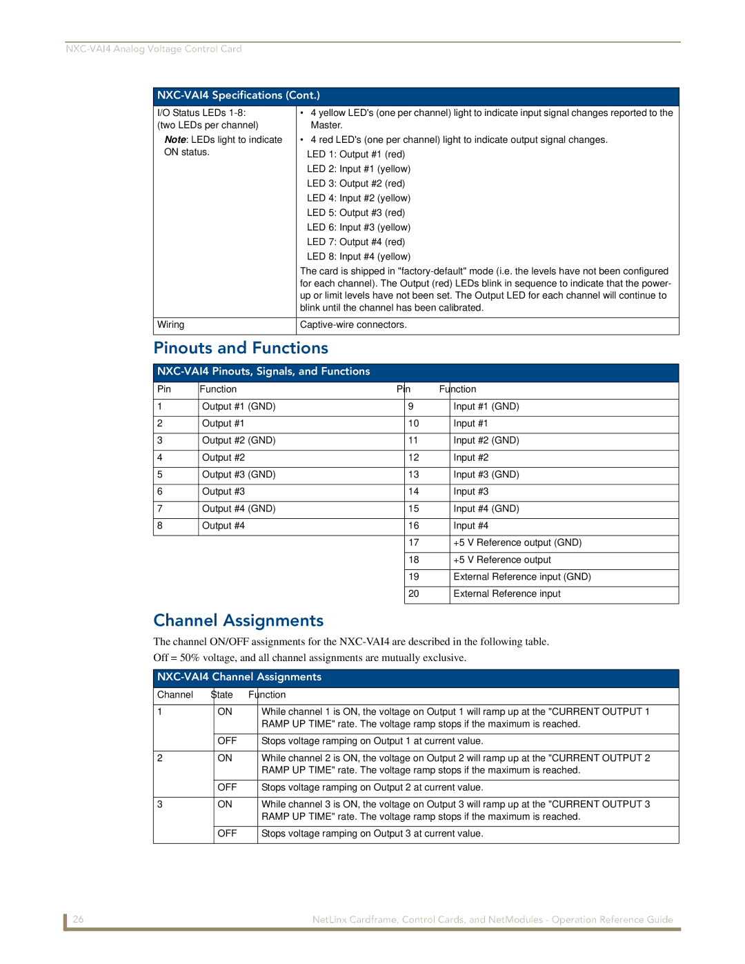
NXC-VAI4 Specifications (Cont.)
I/O Status LEDs | • 4 yellow LED's (one per channel) light to indicate input signal changes reported to the |
(two LEDs per channel) | Master. |
Note: LEDs light to indicate | • 4 red LED's (one per channel) light to indicate output signal changes. |
ON status. | LED 1: Output #1 (red) |
| LED 2: Input #1 (yellow) |
| LED 3: Output #2 (red) |
| LED 4: Input #2 (yellow) |
| LED 5: Output #3 (red) |
| LED 6: Input #3 (yellow) |
| LED 7: Output #4 (red) |
| LED 8: Input #4 (yellow) |
| The card is shipped in |
| for each channel). The Output (red) LEDs blink in sequence to indicate that the power- |
| up or limit levels have not been set. The Output LED for each channel will continue to |
| blink until the channel has been calibrated. |
|
|
Wiring | |
|
|
Pinouts and Functions
NXC-VAI4 Pinouts, Signals, and Functions
Pin | Function | Pin | Function |
|
|
|
|
1 | Output #1 (GND) | 9 | Input #1 (GND) |
|
|
|
|
2 | Output #1 | 10 | Input #1 |
|
|
|
|
3 | Output #2 (GND) | 11 | Input #2 (GND) |
|
|
|
|
4 | Output #2 | 12 | Input #2 |
|
|
|
|
5 | Output #3 (GND) | 13 | Input #3 (GND) |
|
|
|
|
6 | Output #3 | 14 | Input #3 |
|
|
|
|
7 | Output #4 (GND) | 15 | Input #4 (GND) |
|
|
|
|
8 | Output #4 | 16 | Input #4 |
|
|
|
|
|
| 17 | +5 V Reference output (GND) |
|
|
|
|
|
| 18 | +5 V Reference output |
|
|
|
|
|
| 19 | External Reference input (GND) |
|
|
|
|
|
| 20 | External Reference input |
|
|
|
|
Channel Assignments
The channel ON/OFF assignments for the
Off = 50% voltage, and all channel assignments are mutually exclusive.
NXC-VAI4 Channel Assignments
Channel | State | Function |
|
|
|
1 | ON | While channel 1 is ON, the voltage on Output 1 will ramp up at the "CURRENT OUTPUT 1 |
|
| RAMP UP TIME" rate. The voltage ramp stops if the maximum is reached. |
|
|
|
| OFF | Stops voltage ramping on Output 1 at current value. |
|
|
|
2 | ON | While channel 2 is ON, the voltage on Output 2 will ramp up at the "CURRENT OUTPUT 2 |
|
| RAMP UP TIME" rate. The voltage ramp stops if the maximum is reached. |
|
|
|
| OFF | Stops voltage ramping on Output 2 at current value. |
|
|
|
3 | ON | While channel 3 is ON, the voltage on Output 3 will ramp up at the "CURRENT OUTPUT 3 |
|
| RAMP UP TIME" rate. The voltage ramp stops if the maximum is reached. |
|
|
|
| OFF | Stops voltage ramping on Output 3 at current value. |
|
|
|
26 | NetLinx Cardframe, Control Cards, and NetModules - Operation Reference Guide |