NXF CardFrame and NetModules
Device:Port:System (D:P:S)
A device is any hardware component that can be connected to an AXlink or ICSNet bus. Each device must be assigned a unique number to locate that device on the bus. The NetLinx programming language allows numbers in the range 0- 32,767. Device 0 refers to the local Master; numbers greater than 32,767 are reserved.
NetLinx requires a Device:Port:System (D:P:S) specification. This D:P:S triplet can be expressed as a series of constants, variables separated by colons, or a DEV structure. For example:
STRUCTURE DEV
{
INTEGER Number // Device number INTEGER Port // Port on device
INTEGER System // System the device belongs to
}
The D:P:S notation is used to explicitly represent a device number, port and system. For example, 128:1:0 represents the first port on device 128 on this system. If the system and Port specifications are omitted, (e.g. 128), system 0 (indicating this system) and port 1 (the first port) is assumed. Here's the syntax:
NUMBER:PORT:SYSTEM
where:
NUMBER: | |
PORT: | |
| on the Controller or device) |
SYSTEM: |
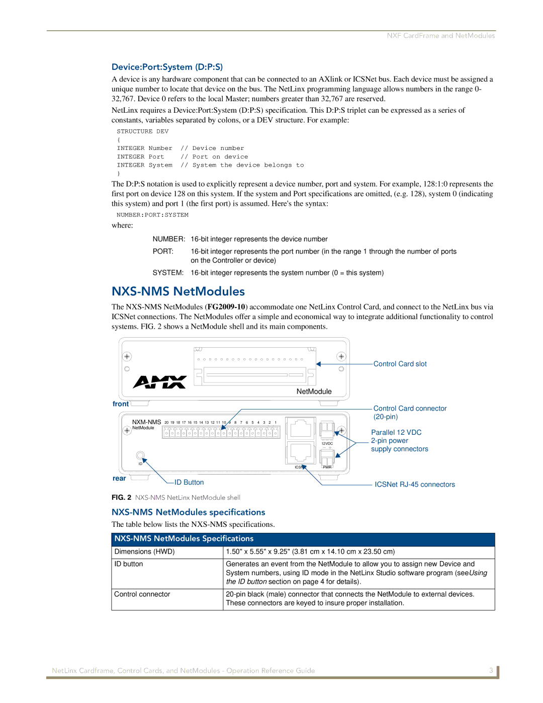
NXS-NMS NetModules
The
|
|
|
|
|
|
|
|
| Control Card slot |
|
|
|
|
|
|
|
| NetModule |
|
front |
|
|
|
|
|
|
|
| Control Card connector |
|
|
|
|
|
|
|
|
| |
8 | 7 | 6 | 5 | 4 | 3 | 2 | 1 | ||
| |||||||||
NetModule |
|
|
|
|
|
|
|
| Parallel 12 VDC |
|
|
|
|
|
|
|
|
| |
|
|
|
|
|
|
|
| 12VDC | |
|
|
|
|
|
|
|
|
| supply connectors |
| ID | PWR |
| ICSNet | |
rear | ID Button | ICSNet |
|
FIG. 2 NXS-NMS NetLinx NetModule shell
NXS-NMS NetModules specifications
The table below lists the
NXS-NMS NetModules Specifications
Dimensions (HWD) | 1.50" x 5.55" x 9.25" (3.81 cm x 14.10 cm x 23.50 cm) |
|
|
ID button | Generates an event from the NetModule to allow you to assign new Device and |
| System numbers, using ID mode in the NetLinx Studio software program (seeUsing |
| the ID button section on page 4 for details). |
|
|
Control connector | |
| These connectors are keyed to insure proper installation. |
|
|
NetLinx Cardframe, Control Cards, and NetModules - Operation Reference Guide | 3 |
|
|