2.4.4 Setting Up the EZ-KIT Lite Hardware
The
The
To connect the
1.Remove the
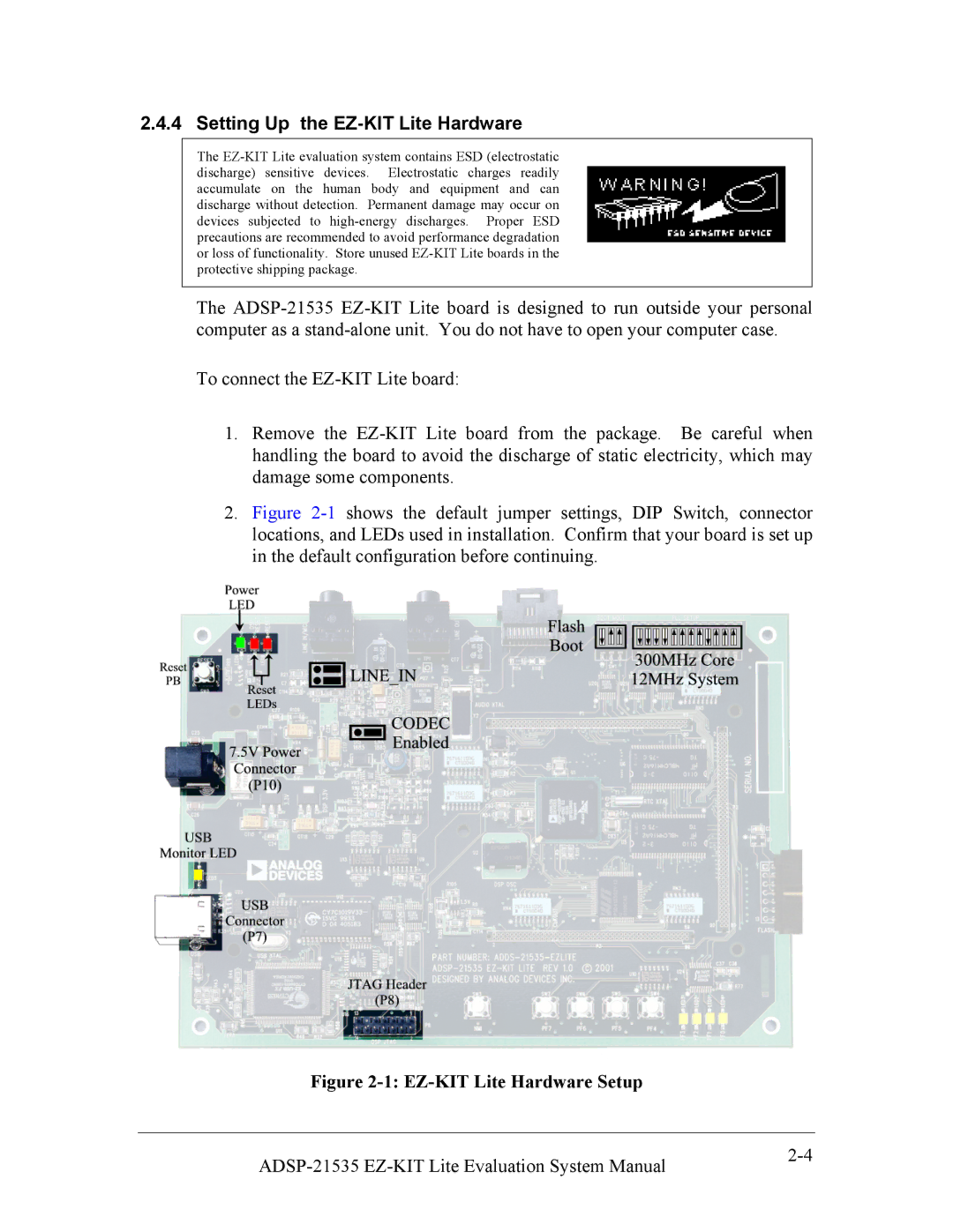
2.Figure 2-1 shows the default jumper settings, DIP Switch, connector locations, and LEDs used in installation. Confirm that your board is set up in the default configuration before continuing.
Figure 2-1: EZ-KIT Lite Hardware Setup
|
