4.4.6Programmable Flag Push Buttons (SW4, SW5, SW6, SW7)
Four push buttons are provided for
Table
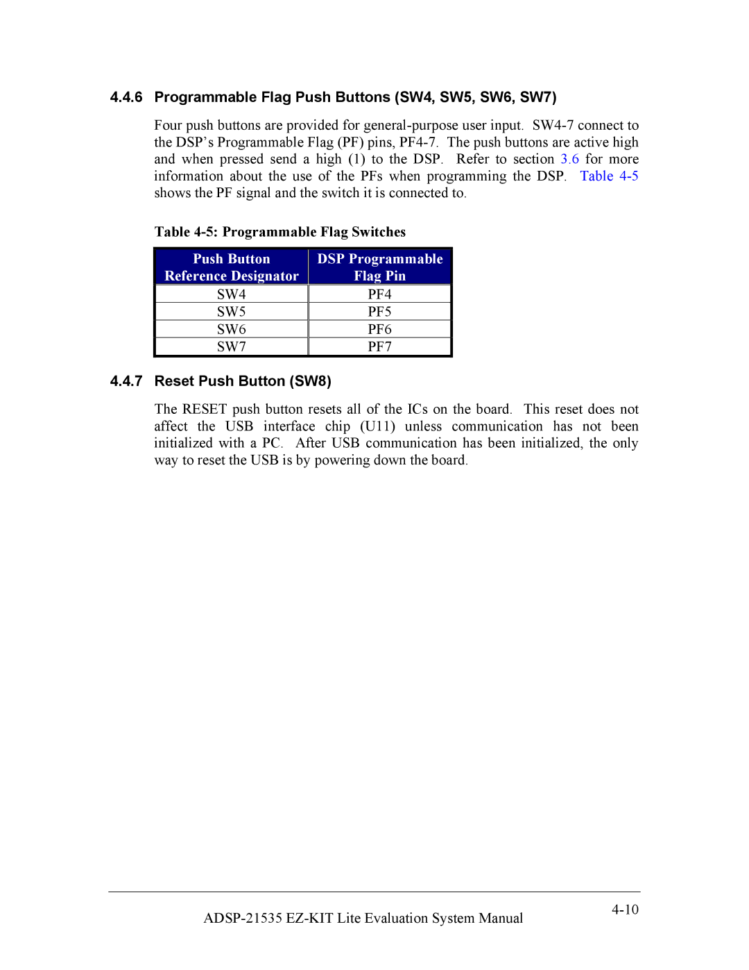
Push Button | DSP Programmable |
Reference Designator | Flag Pin |
SW4 | PF4 |
SW5 | PF5 |
SW6 | PF6 |
SW7 | PF7 |
4.4.7Reset Push Button (SW8)
The RESET push button resets all of the ICs on the board. This reset does not affect the USB interface chip (U11) unless communication has not been initialized with a PC. After USB communication has been initialized, the only way to reset the USB is by powering down the board.
|