High Speed Converter Evaluation Platform
FEATURES
Xilinx
64 kB FIFO depth
Parallel input at 644 MSPS SDR and 800 MSPS DDR Supports 1.8 V, 2.5 V, and 3.3 V CMOS and LVDS interfaces Supports multiple ADC channels up to 18 bits Measures performance with VisualAnalog
Simple USB port interface (2.0)
Supports ADCs with serial port interfaces (SPI)
FPGA reconfigurable via JTAG,
5 V, 3 A switching power supply included Compatible with Windows 98 (2nd edition), Windows 2000,
Windows ME, and Windows XP
EQUIPMENT NEEDED
Analog signal source and antialiasing filter Low jitter clock source
High speed ADC evaluation board and ADC data sheet PC running Windows 98 (2nd edition), Windows 2000,
Windows ME, or Windows XP Latest version of VisualAnalog
USB 2.0 port recommended (USB 1.1 compatible)
HSC-ADC-EVALC
PRODUCT HIGHLIGHTS
1.Easy to Set Up. Connect the included power supply along with the CLK and AIN signal sources to the two evaluation boards. Then connect to the PC via the USB port and evaluate the performance instantly.
2.USB Port Connection to PC. PC interface is via a USB 2.0 connection (1.1 compatible) to the PC. A USB cable is provided in the kit.
3.64 kB FIFO. The
4.Up to 644 MSPS SDR/800 MSPS DDR Encode Rates on Each Channel. Multichannel ADCs with encode rates up to 644 MSPS SDR and 800 MSPS DDR can be used with the ADC capture board.
5.Supports ADCs with Serial Port Interface or SPI. Some ADCs include a feature set that can be changed via the SPI. The ADC capture board supports these
6.VisualAnalog™. VisualAnalog supports the
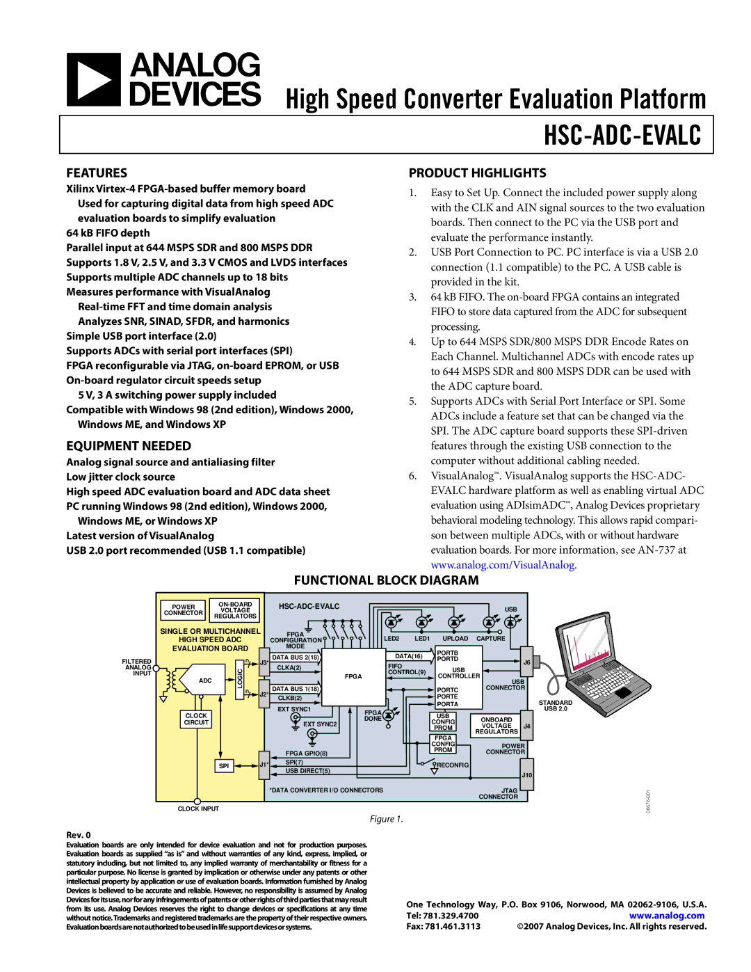
FUNCTIONAL BLOCK DIAGRAM
POWER |
|
|
|
|
| USB |
| |||
CONNECTOR | VOLTAGE |
|
|
|
|
|
|
| ||
REGULATORS |
|
|
|
|
|
|
|
| ||
|
|
|
|
|
|
|
|
| ||
SINGLE OR MULTICHANNEL | FPGA |
| LED2 | LED1 | UPLOAD | CAPTURE |
| |||
HIGH SPEED ADC |
|
| CONFIGURATION |
|
| |||||
EVALUATION BOARD |
| MODE |
| DATA(16) | PORTB |
|
| |||
|
|
|
| DATA BUS 2(18) |
|
|
| |||
FILTERED |
| n | J3* |
| PORTD |
| J6 | |||
|
| FIFO |
|
| ||||||
ANALOG | LOGIC |
|
| CLKA(2) |
|
| USB |
|
| |
INPUT |
|
|
| FPGA | CONTROL(9) |
|
| |||
ADC |
|
|
|
|
| CONTROLLER |
| |||
|
|
|
|
|
|
| USB | |||
| n |
| DATA BUS 1(18) |
|
|
| PORTC | CONNECTOR | ||
|
| J2* |
|
|
| |||||
|
|
| CLKB(2) |
|
|
| PORTE |
| STANDARD | |
|
|
|
|
|
|
|
| |||
|
|
|
| EXT SYNC1 |
|
|
| PORTA |
| |
CLOCK |
|
|
| FPGA |
|
| USB |
| USB 2.0 | |
|
|
|
| DONE |
|
| ONBOARD |
| ||
CIRCUIT |
|
|
| EXT SYNC2 |
|
| CONFIG |
| ||
|
|
|
|
|
| VOLTAGE | J4 | |||
|
|
|
|
|
|
| PROM | |||
|
|
|
|
|
|
|
| FPGA | REGULATORS |
|
|
|
|
|
|
|
|
|
|
| |
|
|
|
|
|
|
|
| CONFIG | POWER | |
|
|
|
| FPGA GPIO(8) |
|
|
| PROM | CONNECTOR | |
| SPI |
| J1* | SPI(7) |
|
|
| RECONFIG |
|
|
|
| USB DIRECT(5) |
|
|
|
|
| |||
|
|
|
|
|
|
|
|
| J10 | |
|
|
|
|
|
|
|
|
|
| |
|
|
|
| *DATA CONVERTER I/O CONNECTORS |
|
|
| JTAG |
| |
|
|
|
|
|
|
|
|
| CONNECTOR |
|
CLOCK INPUT
Figure 1.
Rev. 0
Evaluation boards are only intended for device evaluation and not for production purposes. Evaluation boards as supplied “as is” and without warranties of any kind, express, implied, or statutory including, but not limited to, any implied warranty of merchantability or fitness for a particular purpose. No license is granted by implication or otherwise under any patents or other intellectual property by application or use of evaluation boards. Information furnished by Analog Devices is believed to be accurate and reliable. However, no responsibility is assumed by Analog Devicesforitsuse,norforanyinfringementsofpatentsorotherrightsofthirdpartiesthatmayresult from its use. Analog Devices reserves the right to change devices or specifications at any time without notice.Trademarks and registered trademarks are the property of their respective owners. Evaluationboardsarenotauthorizedtobeusedinlifesupportdevicesorsystems.
One Technology Way, P.O. Box 9106, Norwood, MA
Tel: 781.329.4700 | www.analog.com |
Fax: 781.461.3113 | ©2007 Analog Devices, Inc. All rights reserved. |