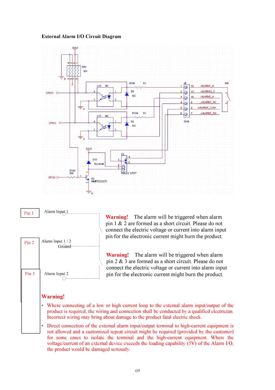
External Alarm I/O Circuit Diagram
Pin 1
Pin 2
Pin 3
Warning! The alarm will be triggered when alarm pin 1 & 2 are formed as a short circuit. Please do not connect the electric voltage or current into alarm input pin for the electronic current might burn the product.
Warning! The alarm will be triggered when alarm pin 2 & 3 are formed as a short circuit. Please do not connect the electric voltage or current into alarm input pin for the electronic current might burn the product.
Warning!
•Where connecting of a low or high current loop to the external alarm input/output of the product is required, the wiring and connection shall be conducted by a qualified electrician. Incorrect wiring may bring about damage to the product fatal electric shock.
•Direct connection of the external alarm input/output terminal to
69