AXIS 223M - Unit Connectors 51
Unit Connectors
This section describes the following:
•The I/O Terminal connector
•Power connections
•The
I/O Terminal connector
The
The terminal connector is used in applications for e.g. motion detection, event triggering, time lapse recording, alarm notification via
•Input - Used for connecting external alarm devices and triggering images for spe- cific
•Output - This can drive a maximum load of 50V DC at 100mA directly or heavier loads by connecting additional relay circuitry. If the output is used with an exter- nal relay, a diode must be connected in parallel with the load for protection against any voltage transients.
Caution!
Connecting AC to the inputs/outputs will damage the unit.
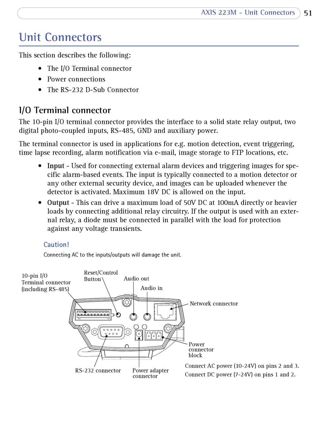
Reset/Control | Audio out |
Button |
Audio in
Network connector
Power connector block
Power adapter | Connect AC power | ||
Connect DC power | |||
| connector |