Preparing for Operation | |
|
|
2.4.3 Relays
1 = NOT USED
2 = NOT USED
3 = NOT USED
4 = NOT USED
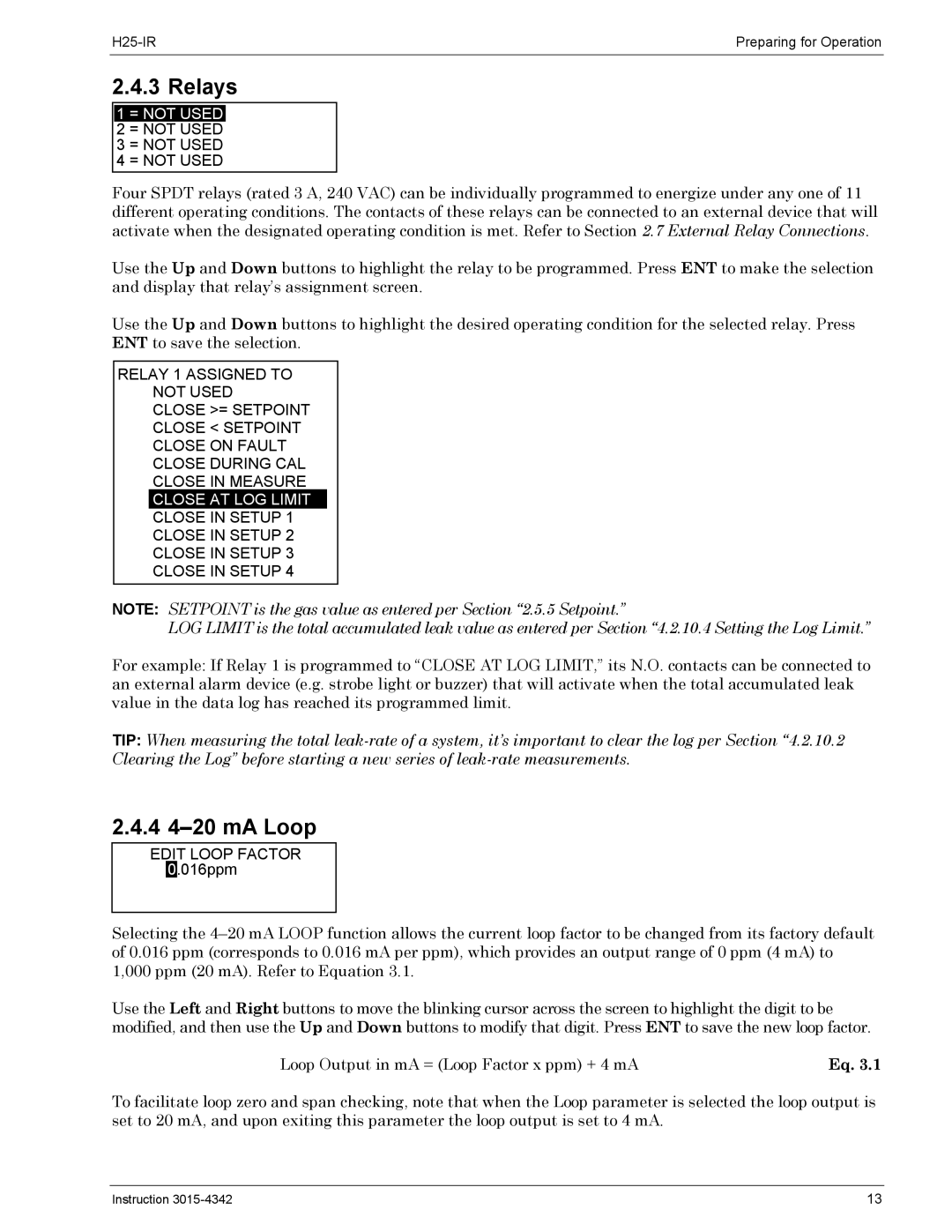
Four SPDT relays (rated 3 A, 240 VAC) can be individually programmed to energize under any one of 11 different operating conditions. The contacts of these relays can be connected to an external device that will activate when the designated operating condition is met. Refer to Section 2.7 External Relay Connections.
Use the Up and Down buttons to highlight the relay to be programmed. Press ENT to make the selection and display that relay’s assignment screen.
Use the Up and Down buttons to highlight the desired operating condition for the selected relay. Press ENT to save the selection.
RELAY 1 ASSIGNED TO
NOT USED
CLOSE >= SETPOINT
CLOSE < SETPOINT
CLOSE ON FAULT
CLOSE DURING CAL
CLOSE IN MEASURE
CLOSE AT LOG LIMIT
CLOSE IN SETUP 1
CLOSE IN SETUP 2
CLOSE IN SETUP 3
CLOSE IN SETUP 4
NOTE: SETPOINT is the gas value as entered per Section “2.5.5 Setpoint.”
LOG LIMIT is the total accumulated leak value as entered per Section “4.2.10.4 Setting the Log Limit.”
For example: If Relay 1 is programmed to “CLOSE AT LOG LIMIT,” its N.O. contacts can be connected to an external alarm device (e.g. strobe light or buzzer) that will activate when the total accumulated leak value in the data log has reached its programmed limit.
TIP: When measuring the total
2.4.4 4–20 mA Loop
EDIT LOOP FACTOR 0.016ppm
Selecting the
Use the Left and Right buttons to move the blinking cursor across the screen to highlight the digit to be modified, and then use the Up and Down buttons to modify that digit. Press ENT to save the new loop factor.
Loop Output in mA = (Loop Factor x ppm) + 4 mA | Eq. 3.1 |
To facilitate loop zero and span checking, note that when the Loop parameter is selected the loop output is set to 20 mA, and upon exiting this parameter the loop output is set to 4 mA.
Instruction | 13 |
