Calibration | |
|
|
3.2 Internal Calibration
Internal calibration uses the instrument’s
The properties of the leak source along with the current internal temperature of the instrument are used to compute the actual leak rate when a calibration is requested. This number is displayed as the “target” value during calibration. A spring switch located in front of the CAL Port ensures that the probe is kept in place for the duration of the calibration process. Calibration will fail if the probe is withdrawn too early in the process, or if the computed parameters deviate from the stored factory calibration by more than 20%.
1.Turn ON instrument and allow it to complete its 120 second
2.Press the front panel CAL button to display the Calibration screen. Note that the display must be reading a leak rate of “0.00” when the CAL button is pressed; otherwise, the message “LEAK RATE MUST BE ZERO TO CALIBRATE” will appear. If necessary, press the ZERO button to zero the display before pressing CAL.
0.89TARGET Oz/yrO/YR R134A
INSERT | R134A | SETUP |
MEASURED | ||
PROBE | O/YR | INT CAL |
3.Ensure that the instrument is set up for internal calibration as indicated by “INT CAL” being displayed at the
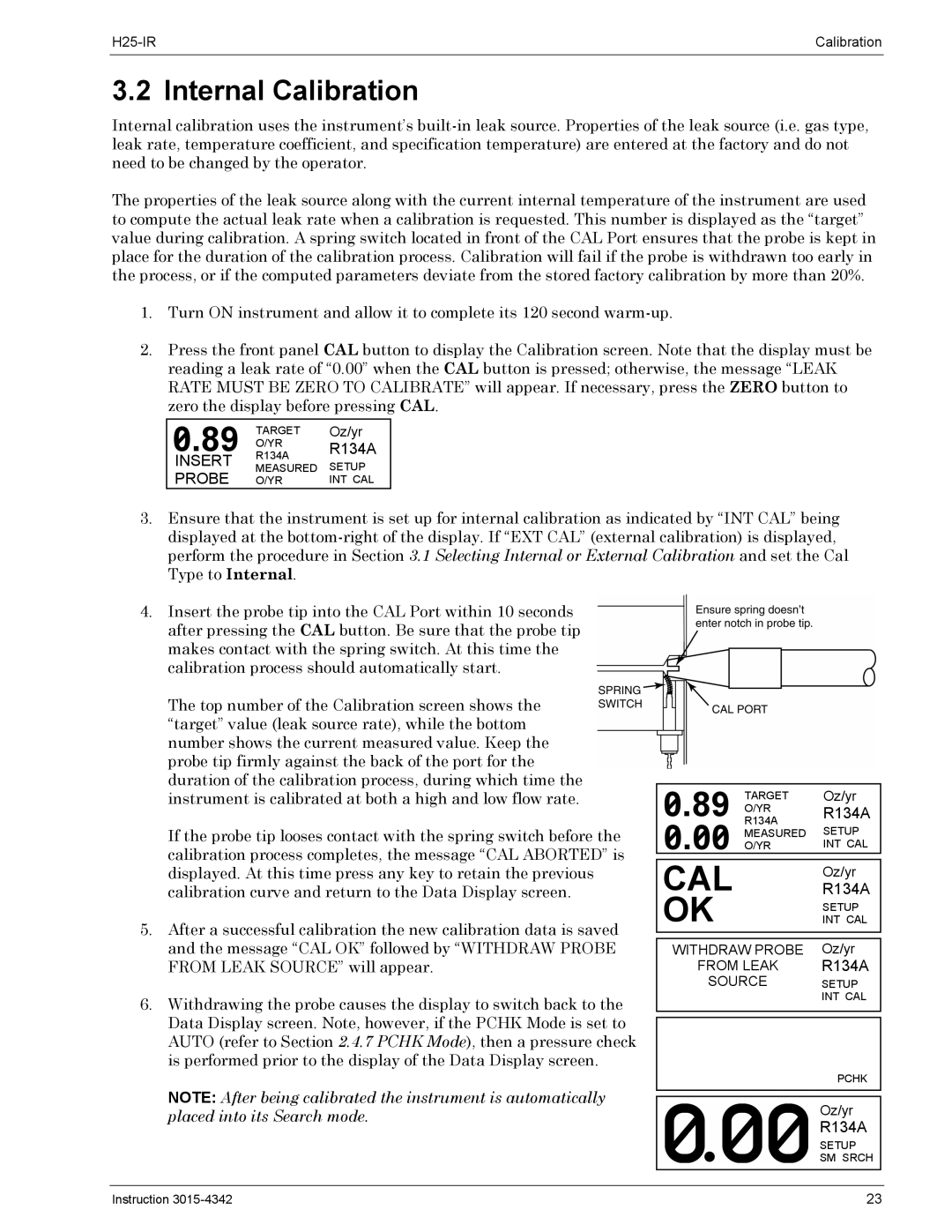
4.Insert the probe tip into the CAL Port within 10 seconds after pressing the CAL button. Be sure that the probe tip makes contact with the spring switch. At this time the calibration process should automatically start.
The top number of the Calibration screen shows the “target” value (leak source rate), while the bottom number shows the current measured value. Keep the probe tip firmly against the back of the port for the duration of the calibration process, during which time the instrument is calibrated at both a high and low flow rate.
If the probe tip looses contact with the spring switch before the calibration process completes, the message “CAL ABORTED” is displayed. At this time press any key to retain the previous calibration curve and return to the Data Display screen.
5.After a successful calibration the new calibration data is saved and the message “CAL OK” followed by “WITHDRAW PROBE FROM LEAK SOURCE” will appear.
6.Withdrawing the probe causes the display to switch back to the Data Display screen. Note, however, if the PCHK Mode is set to AUTO (refer to Section 2.4.7 PCHK Mode), then a pressure check is performed prior to the display of the Data Display screen.
NOTE: After being calibrated the instrument is automatically placed into its Search mode.
0.89 |
|
|
|
| |
TARGET |
| Oz/yr |
| ||
R134AO/YR |
| R134A |
| ||
0.00 | O/YR |
| SETUP |
| |
|
| MEASURED |
|
| |
|
|
|
| INT CAL |
|
|
|
|
|
|
|
|
|
|
|
|
|
| CAL |
|
| R134A | |
| OK |
|
| Oz/yr | |
|
|
| SETUP | ||
|
|
| INT CAL | ||
|
|
|
|
|
|
|
|
|
|
| |
| WITHDRAW PROBE | Oz/yr | |||
| FROM LEAK | R134A | |||
| SOURCE | SETUP | |||
|
|
| INT CAL | ||
|
|
|
|
|
|
PCHK
Oz/yr
R134A
SETUP
SM SRCH
Instruction | 23 |
