APPENDIX A DATA/CONFIGURATION COMMAND SUMMARY
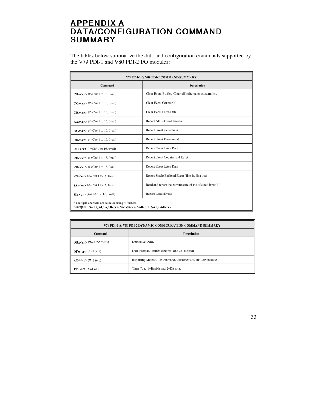
The tables below summarize the data and configuration commands supported by the V79
| V79 | |
Command |
| Description |
CBc<cr> (c=Ch# 1 to 16, 0=all) |
| Clear Event Buffer. Clear all buffered event samples. |
|
|
|
CCc<cr> (c=Ch# 1 to 16, 0=all) |
| Clear Event Counter(s) |
|
|
|
CRc<cr> (c=Ch# 1 to 16, 0=all) |
| Clear Event Latch Data |
|
|
|
RAc<cr> (c=Ch# 1 to 16, 0=all) |
| Report All Buffered Events |
|
|
|
RCc<cr> (c=Ch# 1 to 16, 0=all) |
| Report Event Counter(s) |
|
|
|
RDc<cr> (c=Ch# 1 to 16, 0=all) |
| Report Event Duration(s) |
|
|
|
RLc<cr> (c=Ch# 1 to 16, 0=all) |
| Report Event Latch Data |
|
|
|
ROc<cr> (c=Ch# 1 to 16, 0=all) |
| Report Event Counter and Reset |
|
|
|
RRc<cr> (c=Ch# 1 to 16, 0=all) |
| Report Event Latch Data |
|
|
|
RSc<cr> (c=Ch# 1 to 16, 0=all) |
| Report Single Buffered Event (first in, first out) |
|
|
|
SAc<cr> (c=Ch# 1 to 16, 0=all) |
| Read and report the current state of the selected input(s). |
|
|
|
SLc<cr> (c=Ch# 1 to 16, 0=all) |
| Report Latest Event |
|
|
|
* Multiple channels are selected using 4 formats.
Examples: SA1,2,3,4,5,6,7,8<cr>,
V79 PDI-1 & V80 PDI-2 DYNAMIC CONFIGURATION COMMAND SUMMARY
Command | Description |
DBn<cr> | Debounce Delay |
|
|
DFn<cr> (n=1 or 2) | Data Format. 1=Hexadecimal and 2=Decimal. |
|
|
RMn<cr> (n=1 to 3) | Reporting Method. 1=Command, 2=Immediate, and 3=Schedule. |
|
|
TTn<cr> (n=1 or 2) | Time Tag. 1=Enable and 2=Disable. |
|
|
33