Quick Start
Service Cards
Service Cards
FXO Card
DIP Switch Settings
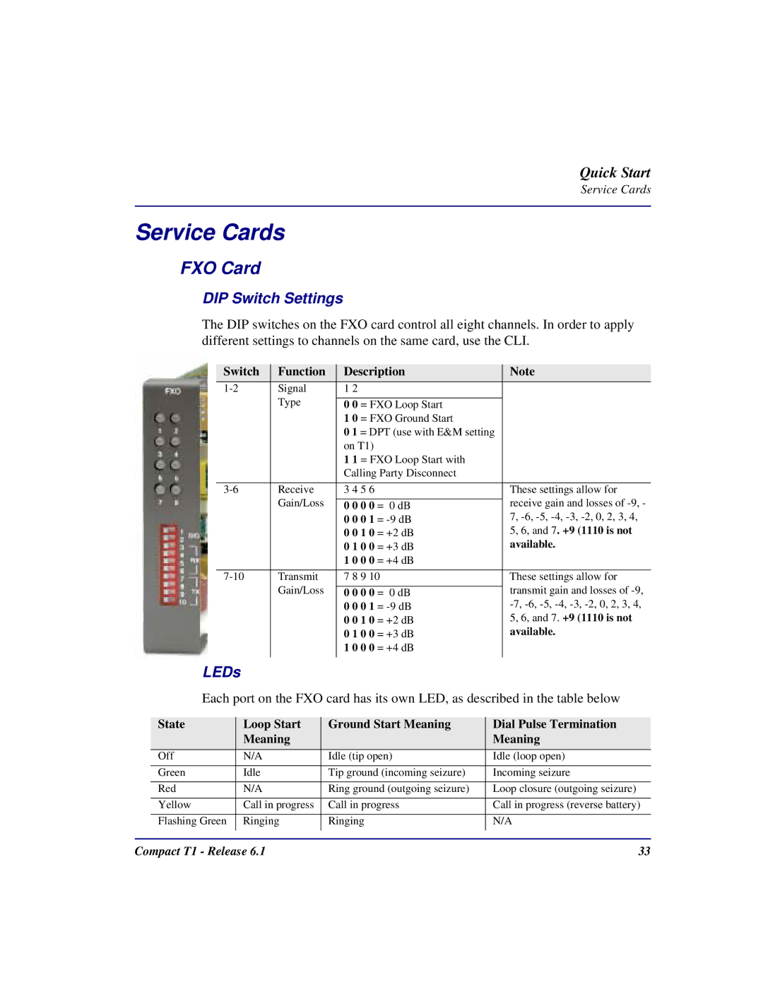
The DIP switches on the FXO card control all eight channels. In order to apply different settings to channels on the same card, use the CLI.
Switch | Function | Description | Note | ||
Signal | 1 2 |
|
|
| |
| Type |
|
| ||
| 0 0 = FXO Loop Start |
| |||
|
| 1 0 = FXO Ground Start |
| ||
|
| 0 1 = DPT (use with E&M setting |
| ||
|
| on T1) |
|
|
|
|
| 1 1 = FXO Loop Start with |
| ||
|
| Calling Party Disconnect |
| ||
|
|
|
|
|
|
Receive | 3 4 5 6 |
|
| These settings allow for | |
| Gain/Loss |
|
| receive gain and losses of | |
| 0 0 0 0 = | 0 dB | |||
|
| 0 0 0 1 | = | 7, | |
|
| 0 0 1 0 | = | +2 dB | 5, 6, and 7. +9 (1110 is not |
|
| 0 1 0 0 | = | +3 dB | available. |
|
| 1 0 0 0 | = | +4 dB |
|
|
|
|
|
| |
Transmit | 7 8 9 10 |
| These settings allow for | ||
| Gain/Loss |
|
| transmit gain and losses of | |
| 0 0 0 0 = | 0 dB | |||
|
| 0 0 0 1 | = | ||
|
| 0 0 1 0 | = | +2 dB | 5, 6, and 7. +9 (1110 is not |
|
| 0 1 0 0 | = | +3 dB | available. |
|
| 1 0 0 0 | = | +4 dB |
|
|
|
|
|
|
|
LEDs
Each port on the FXO card has its own LED, as described in the table below
| State | Loop Start | Ground Start Meaning | Dial Pulse Termination |
|
| Meaning |
| Meaning |
|
|
|
|
|
| Off | N/A | Idle (tip open) | Idle (loop open) |
|
|
|
|
|
| Green | Idle | Tip ground (incoming seizure) | Incoming seizure |
|
|
|
|
|
| Red | N/A | Ring ground (outgoing seizure) | Loop closure (outgoing seizure) |
|
|
|
|
|
| Yellow | Call in progress | Call in progress | Call in progress (reverse battery) |
|
|
|
|
|
| Flashing Green | Ringing | Ringing | N/A |
|
|
|
|
|
Compact T1 - Release 6.1 | 33 |
