MODULAR SMART SWITCH
| LOW port |
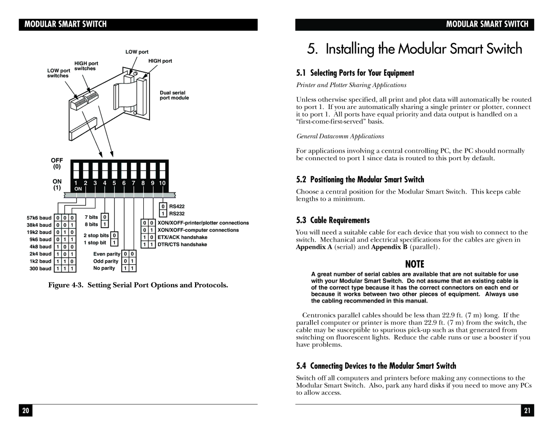
HIGH port | HIGH port |
| |
LOW port switches |
|
switches |
|
Dual serial port module
OFF |
|
|
|
|
|
|
|
|
|
|
|
|
|
|
|
|
|
|
|
|
|
|
|
|
|
|
|
|
|
|
|
|
|
|
|
|
|
|
|
|
|
| |
(0) |
|
|
|
|
|
|
|
|
|
|
|
|
|
|
|
|
|
|
|
|
|
ON |
|
|
|
|
|
|
|
|
|
|
|
|
|
|
|
|
|
|
|
|
|
1 |
| 2 | 3 | 4 | 5 | 6 | 7 | 8 | 9 | 10 |
| ||||||||||
(1) |
| ON |
|
|
|
|
|
|
|
|
|
|
|
|
|
|
|
|
|
| |
MODULAR SMART SWITCH
5.Installing the Modular Smart Switch
5.1Selecting Ports for Your Equipment
Printer and Plotter Sharing Applications
Unless otherwise specified, all print and plot data will automatically be routed to port 1. If you are automatically sharing a single printer or plotter, connect it to port 1. All ports have equal priority and data output is handled on a
General Datacomm Applications
For applications involving a central controlling PC, the PC should normally be connected to port 1 since data is routed to this port by default.
5.2 Positioning the Modular Smart Switch
Choose a central position for the Modular Smart Switch. This keeps cable lengths to a minimum.
|
|
|
|
|
|
|
|
|
|
|
|
|
|
|
|
|
|
|
|
|
|
|
|
|
|
|
|
|
|
|
|
|
|
|
|
|
|
|
|
|
|
57k6 baud | 0 | 0 | 0 | 7 bits | 0 |
|
|
| |||||
38k4 baud | 0 | 0 | 1 | 8 bits | 1 |
|
|
| |||||
19k2 baud | 0 | 1 | 0 | 2 stop bits |
|
| |||||||
0 |
| ||||||||||||
9k6 baud | 0 | 1 | 1 |
| |||||||||
1 stop bit | 1 |
| |||||||||||
4k8 baud | 1 | 0 | 0 |
| |||||||||
|
|
|
|
|
|
| |||||||
2k4 baud | 1 | 0 | 1 |
| Even parity | ||||||||
1k2 baud | 1 | 1 | 0 |
| Odd parity | ||||||||
300 baud | 1 | 1 | 1 |
| No parity | ||||||||
00
01
11
0RS422
1RS232
00
01
10 ETX/ACK handshake
1 1 DTR/CTS handshake
5.3 Cable Requirements
You will need a suitable cable for each device that you wish to connect to the switch. Mechanical and electrical specifications for the cables are given in Appendix A (serial) and Appendix B (parallel).
NOTE
A great number of serial cables are available that are not suitable for use with your Modular Smart Switch. Do not assume that an existing cable is
Figure 4-3. Setting Serial Port Options and Protocols.
20
of the correct type because it has the correct connectors on each end or because it works between two other pieces of equipment. Always use the cabling recommended in this manual.
Centronics parallel cables should be less than 22.9 ft. (7 m) long. If the parallel computer or printer is more than 22.9 ft. (7 m) from the switch, the cable may be susceptible to spurious
5.4 Connecting Devices to the Modular Smart Switch
Switch off all computers and printers before making any connections to the Modular Smart Switch. Also, park any hard disks if you need to move any PCs to allow access.
21