MODULAR SMART SWITCH
Appendix B: Parallel Ports
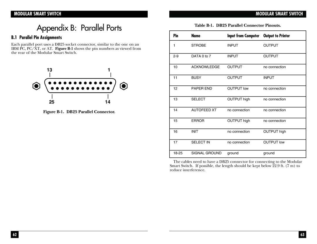
B.1 Parallel Pin Assignments
Each parallel port uses a DB25 socket connector, similar to the one on an IBM PC, PC/XT, or AT. Figure
131
2514
Figure B-1. DB25 Parallel Connector.
MODULAR SMART SWITCH
Table
Pin | Name | Input from Computer | Output to Printer |
|
|
|
|
1 | STROBE | INPUT | OUTPUT |
|
|
|
|
DATA 0 to 7 | INPUT | OUTPUT | |
|
|
|
|
10 | ACKNOWLEDGE | OUTPUT | no connection |
|
|
|
|
11 | BUSY | OUTPUT | INPUT |
|
|
|
|
12 | PAPER END | OUTPUT low | no connection |
|
|
|
|
13 | SELECT | OUTPUT high | no connection |
|
|
|
|
14 | AUTOFEED XT | no connection | no connection |
|
|
|
|
15 | ERROR | OUTPUT high | no connection |
|
|
|
|
16 | INIT | no connection | OUTPUT high |
|
|
|
|
17 | SELECT IN | no connection | OUTPUT low |
|
|
|
|
SIGNAL GROUND | ground | ground | |
|
|
|
|
The cables need to have a DB25 connector for connecting to the Modular Smart Switch. If possible, the length should be kept below 22.9 ft. (7 m) to reduce interference.
62 |
|
|
| 63 |
|
|
|
|
|