MODULAR SMART SWITCH
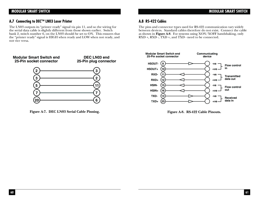
A.7 Connecting to DEC™ LN03 Laser Printer
The LN03 outputs its “printer ready” signal via pin 11, and so the wiring for the serial data cable is slightly different from those shown earlier. Switch bank 2, switch number 6, on the LN03 should be set to ON. This ensures that the “printer ready” signal is HIGH when ready and LOW when not ready, and not vice versa.
MODULAR SMART SWITCH
A.8 RS-422 Cables
The pins and connector types used for
Modular Smart Switch end | DEC LN03 end |
2 | 3 |
3 | 2 |
5 | 11 |
7 | 7 |
20 | 6 |
Modular Smart Switch end | Communicating | |
device | ||
HSOUT- | 9 | |
HSOUT+ | 10 | +ve |
RXD- | 11 | |
RXD+ | 12 | +ve |
HSIN- | 15 | |
HSIN+ | 16 | +ve |
TXD- | 13 | |
TXD+ | 25 | +ve |
Flow control in
Transmitted data out
Flow control out
Received data in
Figure A-7. DEC LN03 Serial Cable Pinning.
Figure A-8. RS-422 Cable Pinouts.
60 |
|
|
| 61 |
|
|
|
|
|