MODULAR SMART SWITCH
6.6 Main Menu
| ADDER TECHNOLOGY | A |
| ADMENU |
| |
| DESTINATION | B |
| FILE TRANSFER | |
| DIRECT OUTPUT | C |
| FUNCTIONS |
| |
| OPTIONS | D |
| PORT 2 | LPT1 |
| |
| <ESC> | TO QUIT | E |
| F | G | H |
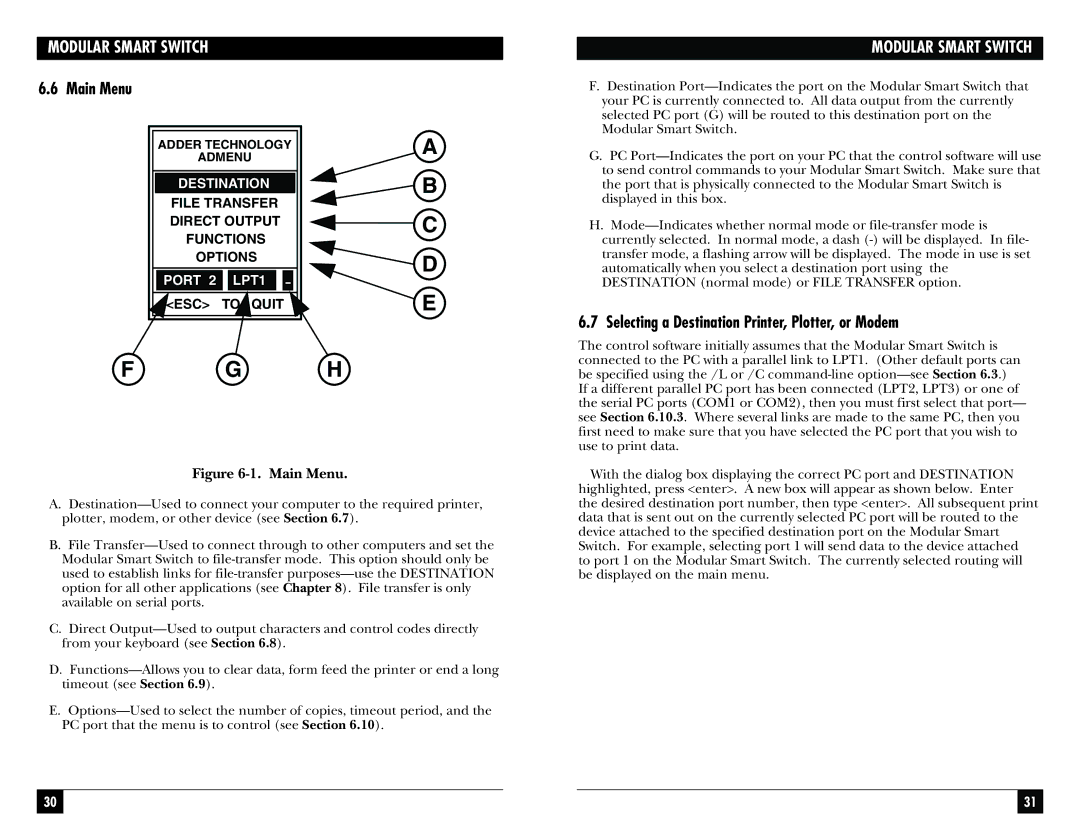
Figure 6-1. Main Menu.
A.Destination—Used to connect your computer to the required printer, plotter, modem, or other device (see Section 6.7).
B.File Transfer—Used to connect through to other computers and set the Modular Smart Switch to file-transfer mode. This option should only be used to establish links for file-transfer purposes—use the DESTINATION option for all other applications (see Chapter 8). File transfer is only available on serial ports.
C.Direct Output—Used to output characters and control codes directly from your keyboard (see Section 6.8).
D.Functions—Allows you to clear data, form feed the printer or end a long timeout (see Section 6.9).
E.Options—Used to select the number of copies, timeout period, and the PC port that the menu is to control (see Section 6.10).
MODULAR SMART SWITCH
F.Destination Port—Indicates the port on the Modular Smart Switch that your PC is currently connected to. All data output from the currently selected PC port (G) will be routed to this destination port on the Modular Smart Switch.
G.PC Port—Indicates the port on your PC that the control software will use to send control commands to your Modular Smart Switch. Make sure that the port that is physically connected to the Modular Smart Switch is displayed in this box.
H.Mode—Indicates whether normal mode or file-transfer mode is currently selected. In normal mode, a dash (-) will be displayed. In file- transfer mode, a flashing arrow will be displayed. The mode in use is set automatically when you select a destination port using the DESTINATION (normal mode) or FILE TRANSFER option.
6.7 Selecting a Destination Printer, Plotter, or Modem
The control software initially assumes that the Modular Smart Switch is connected to the PC with a parallel link to LPT1. (Other default ports can be specified using the /L or /C command-line option—see Section 6.3.) If a different parallel PC port has been connected (LPT2, LPT3) or one of the serial PC ports (COM1 or COM2), then you must first select that port— see Section 6.10.3. Where several links are made to the same PC, then you first need to make sure that you have selected the PC port that you wish to use to print data.
With the dialog box displaying the correct PC port and DESTINATION highlighted, press <enter>. A new box will appear as shown below. Enter the desired destination port number, then type <enter>. All subsequent print data that is sent out on the currently selected PC port will be routed to the device attached to the specified destination port on the Modular Smart Switch. For example, selecting port 1 will send data to the device attached to port 1 on the Modular Smart Switch. The currently selected routing will be displayed on the main menu.