MODULAR SMART SWITCH
To install additional buffer memory:
•Make sure that the Modular Smart Switch is powered off.
•Insert the expansion buffer memory module into slot A or B (slot A should be filled first). A polarizing pin ensures that the board is seated correctly.
The installed buffer memory is automatically tested whenever the Modular Smart Switch is powered on. The buffer memory indicators will flash while the test is in progress and go off when the test is complete. If all the channel and buffer indicators come on permanently, then the buffer has been installed incorrectly or there is a memory fault.
CAUTION
Always observe static handling precautions when installing memory modules.
1.Keep the modules in their
2.Never place memory modules in plastic bags or on plastic surfaces.
3.Discharge static from your clothes before handling the modules (you can do this by touching an
3.2Fitting Port Modules
•Any type of port module can be fitted into any of the six module slots in any order.
•All slots have equal priority.
•All print data is routed by default to port 1 unless a destination port has been selected. For automatic printer and plotter sharing, the printer or plotter should be connected to port 1.
MODULAR SMART SWITCH
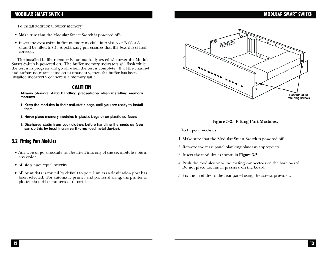
Position of lid
retaining screws
Figure 3-2. Fitting Port Modules.
To fit port modules:
1.Make sure that the Modular Smart Switch is powered off.
2.Remove the rear- panel blanking plates as appropriate.
3.Insert the modules as shown in Figure
4.Push the modules onto the mating connectors on the base board. Do not place too much pressure on the board.
5.Fix the modules to the rear panel using the screws provided.
12 |
|
|
| 13 |
|
|
|
|
|