Maintenance and service
Static Gas Pressure: |
|
| “ WC | |
|
|
|
|
|
|
|
|
| |
P1 Operating Pressure: |
|
| “ WC | |
|
|
|
|
|
The P1 minimum operating gas pressure is 3.5" WC for Natural Gas and 8" WC for Propane. Do not proceed in adjusting CO2 until pressure is at or above these levels, but not to exceed 10.5” WC for Natural Gas and 13” WC for Propane.
A. Once Gas Pressure is adequate
BPress ON/OFF button to turn off the heater.
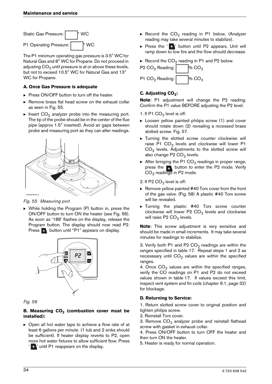
BRemove brass flat head screw on the exhaust collar as seen in Fig. 55.
BInsert CO2 analyzer probe into the measuring port. The tip of the probe should be in the center of the flue pipe (approx 1.5" inserted). Avoid air gaps between probe and measuring port as they can alter readings.
Fig. 55 Measuring port
BWhile holding the Program (P) button in, press the ON/OFF button to turn ON the heater (see Fig. 56). As soon as ‘188’ flashes on the display, release the Program button. The display should now read P2.
Press ![]() button until “P1” appears on display.
button until “P1” appears on display.
Fig. 56
B. Measuring CO2 (combustion cover must be installed):
BOpen all hot water taps to achieve a flow rate of at least 6 gallons per minute. (1 tub and 2 sinks should be sufficient). If heater display reverts to P2, open
more hot water fixtures to allow sufficient flow. Press
‘ ![]() ’ until P1 reappears on the display.
’ until P1 reappears on the display.
B Record the CO2 reading in P1 below. (Analyzer reading may take several minutes to stabilize).
BPress the ‘ ![]() ’ button until P2 appears. Unit will ramp down to low fire and the flow should decrease.
’ button until P2 appears. Unit will ramp down to low fire and the flow should decrease.
BRecord the CO2 reading in P1 and P2 below.
P2 CO2 Reading: |
| % CO2 |
|
| |
P1 CO2 Reading: |
| % CO2 |
|
|
|
C. Adjusting CO2:
Note: P1 adjustment will change the P2 reading. Confirm the P1 value BEFORE adjusting the P2 level.
1. If P1 CO2 level is off:
BLoosen yellow painted philips screw (1) and cover should rotate down (2) revealing a recessed brass slotted screw. Fig. 57.
BTurning the slotted screw counter clockwise will
raise P1 CO2 levels and clockwise will lower P1 CO2 levels. Adjustments to the slotted screw will also change P2 CO2 levels.
BAfter bringing the P1 CO2 readings in proper range,
press the | button to enter the P2 mode. Verify |
CO2 readings in P2 mode. | |
2. If P2 CO2 level is off:
BRemove yellow painted #40 Torx cover from the front of the gas valve. (Fig. 58) A plastic #40 Torx screw will be revealed.
BTurning the plastic #40 Torx screw counter
clockwise will lower P2 CO2 levels and clockwise will raise P2 CO2 levels.
Note: This screw adjustment is very sensitive and should be made in small increments. It may take several minutes for readings to stabilize.
3.Verify both P1 and P2 CO2 readings are within the ranges specified in table 17. Repeat steps 1 and 2 as
necesssary until CO2 values are within the specified ranges.
4.Once CO2 values are within the specified ranges, verify the CO readings on P1 and P2 do not exceed values shown in table 17. If values exceed this limit, inspect vent system and fin coils (chapter 6.1, page 32) for blockage.
D. Returning to Service:
1.Return slotted screw cover to original position and tighten philips screw.
2.Reinstall Torx cover.
3.Remove CO2 analyzer probe and reinstall flathead screw with gasket in exhaust collar.
4.Press ON/OFF button to turn OFF the heater and then turn ON the heater.
5.Heater is ready for normal operation.
34 | 6 720 608 542 |