Manuals
/
Bosch Appliances
/
Household Appliance
/
Water Heater
Bosch Appliances
GWH 2700 ES LP, ESVVT, GWH 2700 ES NG
manual
GWH 2700 ES Functional scheme
Models:
ESVVT
GWH 2700 ES LP
GWH 2700 ES NG
1
1
2
3
4
5
6
7
8
9
10
11
12
13
14
15
16
17
18
19
20
21
22
23
24
25
26
27
28
29
30
31
32
33
34
35
36
37
38
39
40
41
42
43
44
45
46
47
48
49
50
51
52
53
54
55
56
57
58
59
60
60
Download
60 pages
19.85 Kb
43
44
45
46
47
48
49
50
51
52
Troubleshooting
Specification
Back Flow characteristics
Install
Error codes
Electrical diagram
Connecting manometer
Warranty
Dimension
Maintenance
Page 48
Image 48
GWH 2700 ES Functional scheme
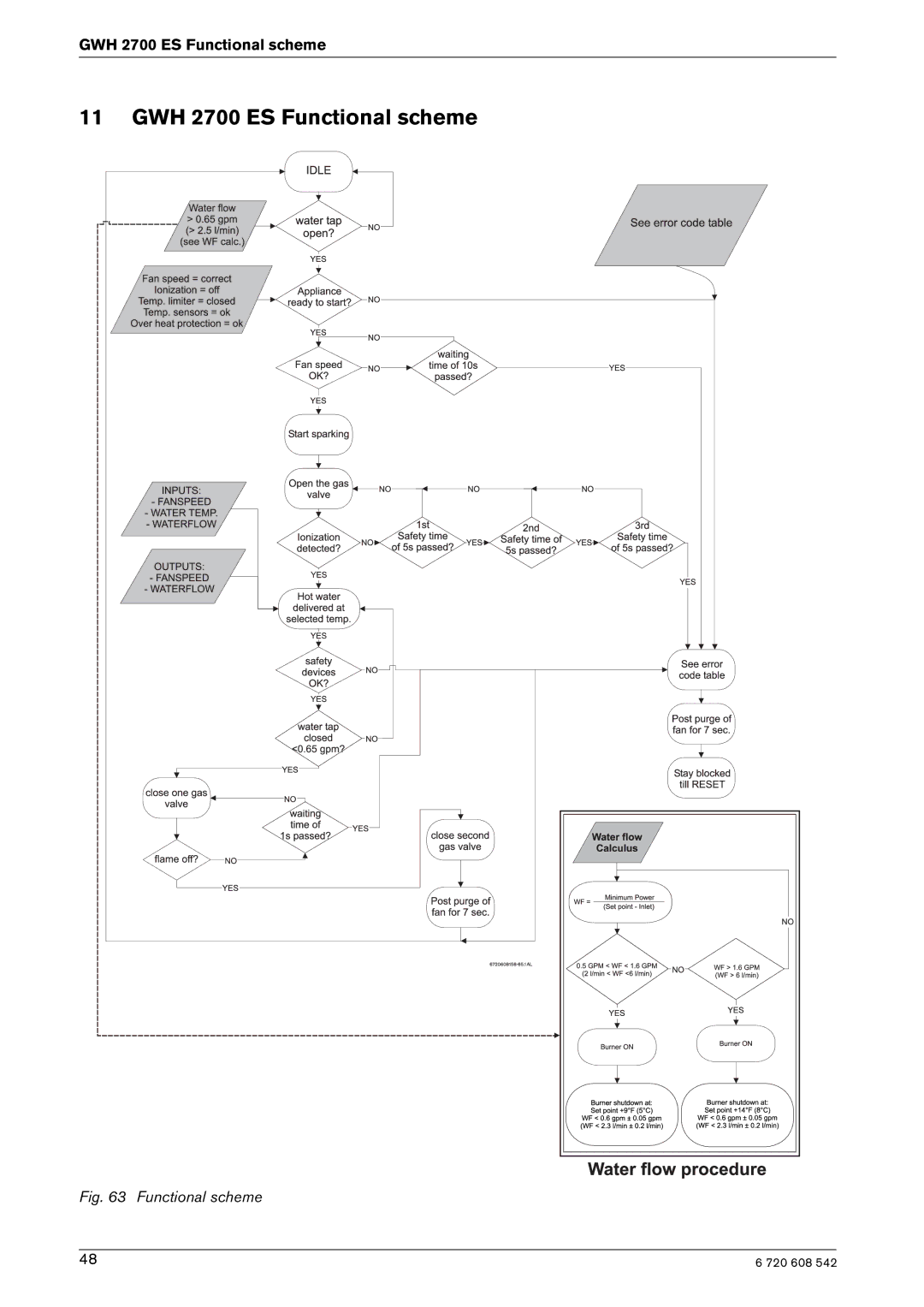
11 GWH 2700 ES Functional scheme
Fig. 63 Functional scheme
48
6 720 608 542
Page 47
Page 49
Page 48
Image 48
Page 47
Page 49
Contents
Intended for variable flow applications
What to do if you smell gas
Index
For your safety
Features
Appliance details
Specifications Technical data
To remove combustion cover service only
Unpacking the heater
GWH 2700 ES is not approved or designed for
General rules to follow for safe operation
Venting
Dimensions and Minimum installation clearances
Dimensions
Installation instructions
Tools required for installation
Introduction
Venting
Installation instructions Horizontal venting systems only
Venting Specifications
Fittings or Piping Equivalent Feet
Installation instructions Condensate drain requirements
Twin pipe termination clearances
Minimum combustion air and exhaust pipe length
Maximum combustion air and exhaust pipe length
Canadian installations1 Installations2
Canadian installations1
Horizontal twin pipe penetration
Vertical venting installation twin pipe penetra- tion
Vent connections
Installation instructions Condensate drain installation
Venting Flex ProTech Heat Fab
Total equivalent vent length calculation
Exhaust
Intake
Example
Adjusting minimum power fan speed P2
Adjusting maximum power fan speed P1
Level Vent length1 Speed P2
Installation instructions
Combustion air requirements
Twin pipe and Concentric pipe
Proper location for installing your heater
Heater placement and clearances
Mounting installation
Gas piping & connections
GAS Line Sizing
For Natural GAS
Water connections
Water quality
Domestic hot water recirculation
GWH
Connecting manometer
Measuring gas pressure
Static Pressure Test
Operating Pressure Test
Electrical power supply
Electrical connections
Position of the fuses in control unit
Operation instructions
LCD Display functions
For your safety read before operating your water heater
Power
Temperature selection
Use of optional remote control Accessory part no. TSTAT2
Reset button
Operation
Program button
Maintenance and service
Annual maintenance table Every year
Annual maintenance
Winterizing for seasonal use
Adjusting CO2 carbon dioxide
Descaling using a pump
Mineral scale build-up
Measuring CO2 combustion cover must be installed
Adjusting CO2
Returning to Service
Once Gas Pressure is adequate
Final Readings
% 3.0 % 60 ppm
Program Description Factory Default
Program values
Comment
Control board diagnostics
Diagnostic menu
Troubleshooting
Troubleshooting
Water is too hot
Water is not hot enough
Hot water temperature fluctuates at tap
Low water flow/pressure
Noisy burner/heater during operation
Lack of adequate gas pressure. Inadequate gas
Problem solving
Error code diagnostics
Problem solving Display Cause Solution
Venting may cause this failure
Over-temperature detected by
No flame ionization detected with
Electrical diagram
Electrical diagram
Sensor resistance charts
Back Flow characteristics
GWH 2700 ES Functional scheme
Functional scheme
Interior components diagram and parts list
Interior components diagram and parts list
Interior components
Appliance overview
Components diagram
Group
Description Reference
Interior components diagram and parts list Group
1211
6720608158-73.1AL
Interior components diagram and parts list Group
708 300
Protecting the environment
Protecting the environment
Packing
Components
Limited Warranty
Limited Warranty
6720608542
Top
Page
Image
Contents