Installation instructions
Fig. 25 Leveling the mounting bracket on the studs
Fig. 26 Mounting the heater
Warning: Appliance must be installed vertically.
3.8Gas piping & connections
Before connecting the gas supply, check the rating plate on the right side of the heater to be sure that the heater is rated for the same gas to which it will be connected.
In the United States: The installation must conform with local codes or, in the absence of local codes, the National Fuel Gas Code ANSI Z223.1/NFPA 54.
In Canada: The Installation must conform to CSA B149 INSTALLATION CODES and/or local installation codes.
Warning: DO NOT connect to an unregulated or high pressure propane line or to a high pressure commercial natural gas line.
Warning: The heater must be isolated from the gas supply piping system during any pressure testing of that system at test pressures equal to or more than 0.5 psig. If overpressure has occurred, such as through improper testing of the gas lines or malfunction of the supply system, the gas valve must be checked for safe operation.
GAS CONNECTIONS
BInstall a manual gas shut off valve on the gas supply line within easy reach of the appliance.
BInstall a union when connecting gas supply.
BThe minimum internal diameter required for any appliance connector is ¾”.
BUndersized flexible appliance connectors not permitted.
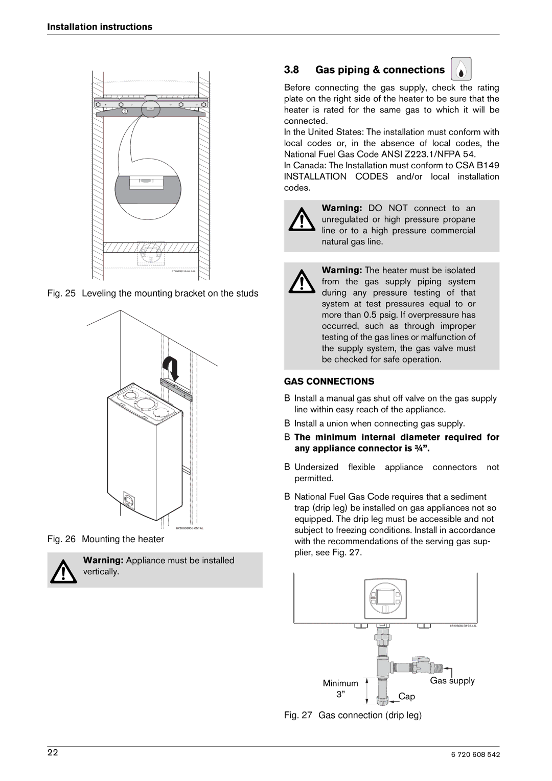
BNational Fuel Gas Code requires that a sediment trap (drip leg) be installed on gas appliances not so equipped. The drip leg must be accessible and not subject to freezing conditions. Install in accordance with the recommendations of the serving gas sup- plier, see Fig. 27.
Minimum
3”
Gas supply
Cap
Fig. 27 Gas connection (drip leg)
22 | 6 720 608 542 |