FEATURES/BENEFITS
542J150,180
548F036-072 548F090-120 549B036-072 549B090-120
Table of Contents
Service Options
Integrated ECONOMI$ERS and Outdoor AIR
INDOOR-AIR Quality Begins with Bryant Rooftops
Options and Accessories
Option ACCESSORY†
Options and Accessories
Barometric RELIEF/POWER Exhaust
LOW Ambient Controls
Emergency Heat Control Package
DURA-SHIELDOUTDOOR Coil Options
Outdoor Coil Protection Applications
Electric Heaters
ECONOMI$ER Microprocessor Controller
Convenience Outlet
Glycol Coil 150,180 only
Hail Guard
Bryant Commercial Programmable Thermostat
Compressor Hinged Panel Option
Control BOX Hinged Panel Option
Options and Accessories
Controls
Cooling, Units With EconoMi$er 548F036-072 and 549B036
Controls
Sequence of Operation 542J150,180
Controls
Typical Smoke Control/Fire Shutdown Wiring 542J150,180
Operating Modes
Application Data
Application Data
Concentric Duct Distribution 542J150,180
Concentric Duct Details 542J150,180
Typical Piping and Wiring
Horizontal Discharge Ducting 548F036-120 and 549B036-120
Vertical Discharge Ducting 548F036-120 and 549B036-120
Typical Piping and Wiring
Model Number Nomenclature 548F Units
ODS Model Number
ARI* Capacity Ratings
Physical Data
548F036-072
Physical Data
548F090-120
072-548F036
Base Unit Dimensions
Accessory Dimensions
Connector ALT GAS Power Control PKG. Accy Drain Hole
Roof Curb Unit Size Accessory CRRFCURB001A00
CRRFCURB002A00
Accessory Dimensions
Selection Procedure with 548F048 Example
Determine Cooling and Heating Loads AT Design Conditions
II Select Unit Based on Required Cooling Capacity
III Select Electric Heat
Performance Data
Cooling Capacities
SHC
Entering AIR DRY-BULB Temp F
Performance Data
Cooling Capacities
Entering AIR DRY-BULB Temp F Bypass
Air Temperature Entering Outdoor Coil F
Instantaneous and Integrated Heating Ratings
4100/0.18 4700/0.21
Under
Instantaneous and Integrated Heating Ratings
1800 Cap
2400 Cap
3000 Cap
2600 Cap
Cfm
Standard Air 2400 Cap
3600 Cap
4000 Cap
FAN Performance Vertical Discharge Units
548F036 3 Tons Standard Motor Direct Drive
ESP
548F036 3 Tons Alternate Motor Belt Drive
FAN Performance Vertical Discharge Units
548F048 4 Tons Alternate Motor Belt Drive
548F060 5 Tons Standard Motor Direct Drive
ESP
548F060 5 Tons Alternate Motor Belt Drive
548F060 5 Tons HIGH-STATIC Motor Belt Drive
548F072 6 Tons HIGH-STATIC Motor Belt Drive
Rpm Bhp Watts
511 539
518 562
534 607
548F090 71/2 Tons HIGH-STATIC Motor Belt Drive
548F102 8 TONS* Standard Motor Belt Drive
548F102 81/2 Tons HIGH-STATIC Motor Belt Drive
548F120 10 Tons
Rpm Bhp
963 2651
973 2782
FAN Performance Horizontal Discharge Units
Airflow Low Speed High Speed Cfm 208 230, 460, 575
Cfm Rpm Bhp Watts
FAN Performance Horizontal Discharge Units
548F048 4 Tons Alternate Motor Belt Drive
658 276 722 337 840 470
693 327 754 388 867 531
729 388 787 450 895 593
765 460 821 521
548F060 5 Tons HIGH-STATIC Motor Belt Drive
548F072 6 Tons Standard Motor Belt Drive
Rpm Bhp Watts 1800 942 700 1047 835 1139 956
1031 1276
1900 982 779 1084 932 1160 1006
1114
Rpm Bhp Watts 2250 465 473 554 630
2300 471 487 559 646
2400 482 524 569 684
2500 494 554 581 723
Rpm Bhp Watts 2250 507 547 586 700 658 891 722 1097 783
2300 513 562 592 723 663 916 727 1131 786
2400 528 600 606 779 674 965 738 1199 795
2500 542 648 619 835 686 1022 748 1258 806
548F102 81/2 Tons Standard Motor Belt Drive
Rpm Bhp Watts 2550 669 627 867 692 1056 754 1292 812
2900 604 867 676 1089 737 1318 794 1560 848
3100 636 1006 704 1241 764 1499 818 1744
3200 652 1089 718 1327 778 1595 831 1849
General Notes for FAN Performance Tables
ACCESSORY/FIOP Static PRESSURE* in. wg 548F036-072
ACCESSORY/FIOP Static PRESSURE* in. wg 548F090-120
FAN RPM AT Motor Pulley SETTINGS* 548F036-120
Component CFM
Optional Power Exhaust
EconoMi$er Barometric Relief Damper Characteristics
Power Requirements
Mocp Size
Electric Heating Capacities
Multiplication Factors
Heater Rating
Distribution
INDOOR-FAN Motor Performance 548F Units
Unit INDOOR-FAN Maximum Acceptable Motor
Operating Watts AMP Draw Efficiency %
090
Electrical Data
Units Without Electrical Convenience Outlet
Electrical Data
Units Without Electrical Convenience Outlet
Voltage Compressor Electric Heat Power Supply Disconnect
Nominal IFM Range
OFM IFM SIZE†
Tons
81/2 Tons
Units with Electrical Convenience Outlet
Units with Electrical Convenience Outlet
40.4 45†† 195/195 13.6/15.6 57.4 59.9 60†† 208/211
Voltage Compressor Electric Power Supply Disconnect
Unbalanced 3-Phase Supply Voltage
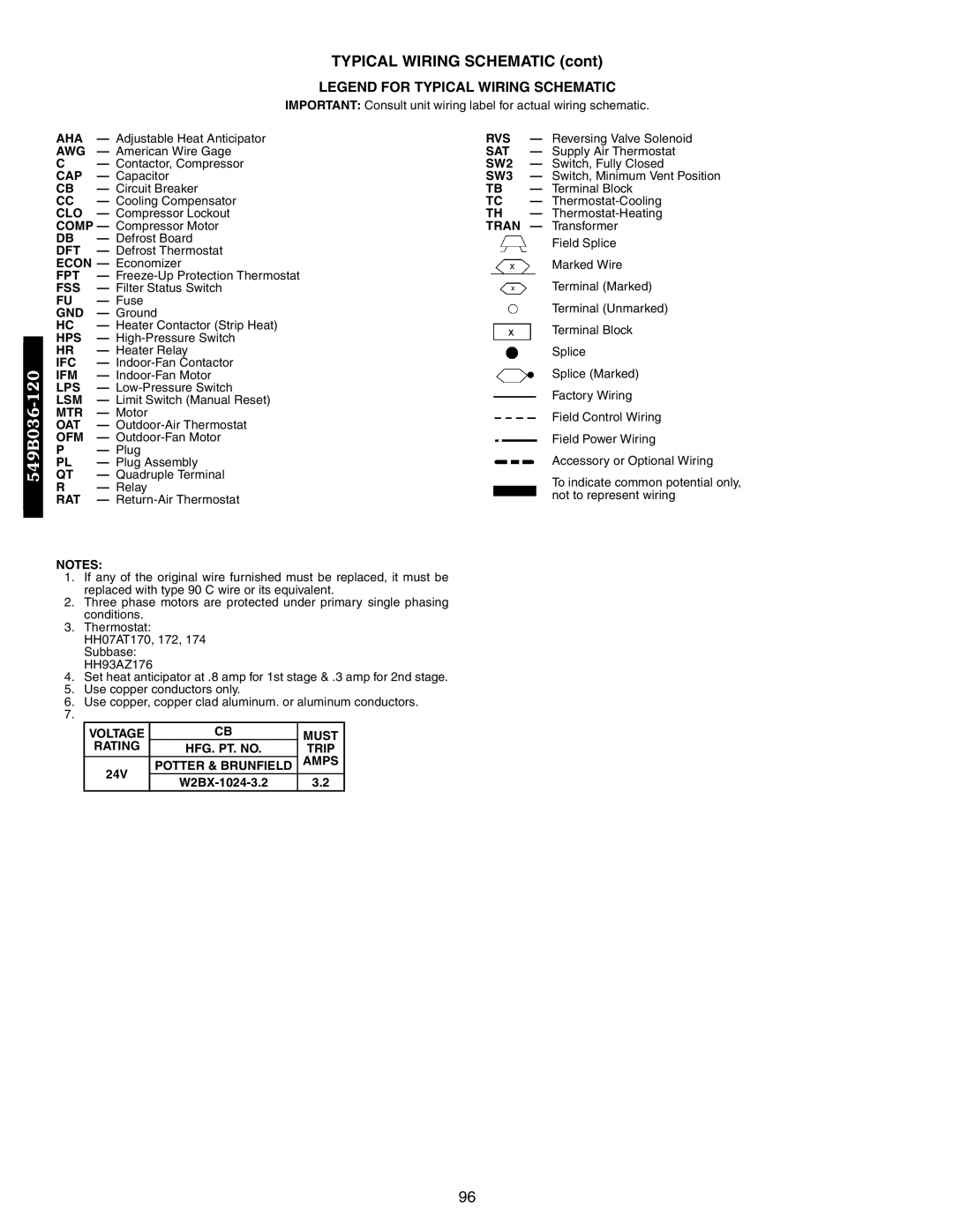
Typical Wiring Schematic
SW4
Typical Wiring Schematic
Outdoor-Fan Motor
Model Number Nomenclature
549B E X 090 000 AA
549B036-060
549B072-120
549B036-072
Base Unit 549B
549B090,120
Base Unit Dimensions
549B036-120 549B090,120
′-2 ″
549B036-072
′-0 ″
″ 19 NPT 827 583 44.5 12.7 NPT
Selection Procedure with 549B048 Example
II Select Unit Based on Required Cooling
Capacity
Enter Cooling Capacities table at outdoor entering temper
SHC
Entering AIR DRY-BULB Temp F Bypass
Factor
549B072 6 Tons Temp F
1800/0.06 2100/0.066 2400/0.071 3000/0.088 Entering Air
549B090 71/2 Tons Temp F
2250/0.12 3000/0.15 3750/0.18 Entering Air
549B036 3 Tons
900 Cap
549B048 4 Tons
549B060 5 Tons
549B072 6 Tons
2100 Cap
Temperature Air Entering Outdoor Coil F db at 70% rh
549B090 71/2 Tons
549B120 10 Tons
Rpm Bhp 900
673 736 805 865 911 1000
709 782 835 900 937 1100
746 806 867 929 964 1200
549B060 5 Tons Standard Motor Belt Drive
549B072 6 Tons Standard Motor Belt Drive
549B090 71/2 Tons Standard Motor Belt Drive
549B120 10 Tons Standard Motor Belt Drive
584 656 734 818 875 1000
627 738 800 848 895 1100
670 758 812 863 914 1200
710 780 840 889 938 1300
Cfm Rpm Bhp 1500 1108 1187 1202 1079
2100 1252 1320 1388 1448
1372
Airflow External Static Pressure in. wg
Rpm Bhp 2250
630 695
635 699
645 708
595 657 716 770
605 667 725 779
615 679 734 787
625 691 744 796
ACCESSORY/FIOP Static PRESSURE* in. wg 549B036-072
ACCESSORY/FIOP Static PRESSURE* in. wg 549B090,120
FAN RPM AT Motor Pulley SETTINGS* 549B036-120
549B 036
INDOOR-FAN Motor Data 549B036-120
Outdoor Sound Power Total Unit
Electric Heating Capacities
Nominal Voltage Electric Power Minimum Unit Compressor OFM
Disconnect Voltage Range Heat Supply
RLA LRA
FLA MCA Mocp LRA
Nominal Voltage Electric Power Minimum Unit Compressor
IFM Disconnect Voltage Range Heat Supply
Ph-Hz Min Max
RLA LRA FLA
30.4 106/106
43.0 247/247 10.4 21.7 25.0 70.1 74.3 269/272
Typical Wiring Schematic
Must
Rating HFG. PT. no Trip
Potter & Brunfield Amps
RVS
Guide Specifications 548F and 549B036-120 Units
Part 1 General
Part 2 Products
Guide Specifications 548F and 549B036-120 Units
Guide Specifications 548F and 549B036-120 Units
100
Model Number Nomenclature 542J150,180 Units
542J E X 150 000 AB H B
Weight Distribution and Center of Gravity
Unit Weight Weight of Corner Dimensions
542J150,180 Units
Cooling HEATING-HIGH Temp HEATING-LOW Temp Sound Unit
Unit 542J
STD
ALT
STD ALT
Unit Maximum Shipping Weight
Unit Dimensions
Unit Weight of Corner
542J 150 1895 860 180 2205 1000
DIMENSIONS* degrees and inches
PKG NO. REF Curb Description Height CRRFCURB010A00
CRRFCURB011A00
CRRFCURB012A00
Horizontal Adapter Installation 542J150,180
Accessory Curb Description
Convenience Outlet 542J150,180
Height
Power Exhaust 542J150,180
Non-Fused Disconnect 542J150,180
Selection Procedure with 542J180 Example
Capacity TC of 180,800 Btuh, a sensible heat capacity
542J150 Temp F Air Entering Indoor Coil Cfm/BF
542J180
Integrated Heating Capacities
5625
CFM
General Notes for FAN Performance Tables
ACCESSORY/FIOP Static PRESSURE* in. wg 542J150,180
FAN RPM AT Motor Pulley SETTINGS* 542J150,180
Fan Performance Using Accessory Power Exhaust
ACCESSORY/FIOP Unit Size Unit Voltage CFM
Electric Heating Capacities 542J150,180
Glycol Coil Data
Glycol Coil Ratings
INDOOR-FAN Motor Performance 542J150,180
542J180, 460-3-60 Shown
BKR W/AT
LOR
LPS
CAP
Optional Non-Fused Disconnect 542J150,180
Guide Specifications 542J150,180 Units
Part 1 General
Part 2 Products
Guide Specifications 542J150,180 Units
120
121
Index
95,96