FEATURES/BENEFITS
EASY MAINTENANCE AND INSTALLATION
551B036-072 558F036-073 551B090-150 551A155,180558F090-150
558F180-210 559F180-216 558F300 558F240 559F240-300
Single-Point Electrical Power Connections permit easier
SERVICEABILITY
QUIET, EFFICIENT OPERATION AND DEPENDABLE PERFORMANCE
Totally Enclosed Condenser Fan Motors and permanently
TABLE OF CONTENTS
Guide Specifications - Sizes
558F036-150
558F180-300
OPTIONS AND ACCESSORIES
2. Some options may increase product lead times
BAROMETRIC RELIEF/POWER EXHAUST 155-300 Shown
OPTIONS AND ACCESSORIES cont
LOW AMBIENT CONTROLS
DURA-SHIELD CONDENSER COIL OPTIONS
CONDENSER COIL PROTECTION APPLICATIONS
Perfect Humidity DEHUMIDIFICATION PACKAGE
Dura-Shield Option
LIGHT COMMERCIAL THERMIDISTAT
TIME GUARD CONTROL
DURABLADE ECONOMIZER
BRYANT COMMERCIAL THERMOSTAT
CONVENIENCE OUTLET
UNIT-MOUNTED DISCONNECT Sizes
Factory-installed, internally-mounted, NEC National Electri- cal Code and UL Underwriters’ Laboratories approved non-fused switch provides unit power shutoff with disconnect lockout protection capability. The switch is accessible from outside the unit
HAIL GUARD
COIL GUARD GRILLE 036-150 Only
CONTROL BOX HINGED PANEL OPTION 581B036-072 UNITS
COMPRESSOR HINGED PANEL OPTION 581B090-150 UNITS SHOWN
EVAPORATOR-FAN HINGED PANEL OPTION
FILTER HINGED PANEL OPTION
LP CONVERSION KIT
581B036-072
OPERATING SEQUENCE - SIZE 036-073 UNITS
CONTROLS
OPERATING SEQUENCE - SIZE 090-150 UNITS
CONTROLS cont
SEQUENCE OF OPERATION SIZES
Perfect Humidity Dehumidification Option
TYPICAL WIRING SCHEMATIC Single Fan Units, Sizes
EconoMi$er
TYPICAL WIRING SCHEMATIC Two-Fan Units, Size
ACTUATOR
TYPICAL WIRING SCHEMATIC Sizes
3. Jumpers are omitted when unit is equipped with EconoMi$er
EconoMi$er Wiring
TYPICAL WIRING SCHEMATIC cont
Non-Fused Disconnect Optional
Vertical Discharge Ducting
TYPICAL PIPING AND WIRING - SIZES
Horizontal Discharge Ducting
2. Installation must comply with all applicable codes
APPLICATION DATA
10. MAXIMUM OPERATING OUTDOOR-AIR TEMPERATURE
12. PERFECT HUMIDITY DEHUMIDIFICATION PACKAGE
Concentric Duct Distribution Unit Sizes
Applications
APPLICATION DATA cont
c. MUSEUMS AND LIBRARIES - Humidity can damage books and artwork
15. PERFECT HUMIDITY DEHUMIDIFICATION PACKAGE FEATURES AND BENEFITS
Pressure Enthalpy Curve
Psychrometric Chart 551B072 Shown
Without Subcooler
Point 3 - Leaving Air F 63.0 db/56.8 wb With Subcooler
db - Dry Bulb wb - Wet Bulb
MODEL NUMBER NOMENCLATURE - 558F
558F036
ARI* CAPACITY RATINGS
558F E X 090 000 KB
PHYSICAL DATA - 558F036-073
558F036
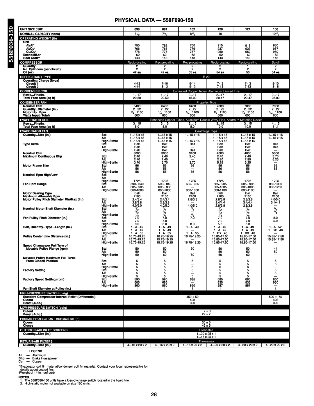
PHYSICAL DATA - 558F090-150
558F036
BASE UNIT DIMENSIONS - 558F036-072
558F036-150
BASE UNIT DIMENSIONS - 558F073
BASE UNIT DIMENSIONS - 558F090,102,120,150
558F036-150
BASE UNIT DIMENSIONS - 558F091,121
ACCESSORY DIMENSIONS
ACCESSORY DIMENSIONS cont
SELECTION PROCEDURE with 558F048 example
I DETERMINE COOLING AND HEATING REQUIRE- MENTS AT DESIGN CONDITIONS
II SELECT UNIT BASED ON REQUIRED COOLING CAPACITY
III SELECT ELECTRIC HEAT
COOLING CAPACITIES
PERFORMANCE DATA
over
PERFORMANCE DATA cont
COOLING CAPACITIES cont
PERFORMANCE DATA cont
558F036-150
COOLING CAPACITIES cont
PERFORMANCE DATA cont
FAN PERFORMANCE - VERTICAL DISCHARGE UNITS
FAN PERFORMANCE - VERTICAL DISCHARGE UNITS cont
PERFORMANCE DATA cont
558F036-150
FAN PERFORMANCE - VERTICAL DISCHARGE UNITS cont
558F036-150
PERFORMANCE DATA cont
FAN PERFORMANCE - VERTICAL DISCHARGE UNITS cont
PERFORMANCE DATA cont
558F036-150
FAN PERFORMANCE - VERTICAL DISCHARGE UNITS cont
558F036-150
PERFORMANCE DATA cont
FAN PERFORMANCE - VERTICAL DISCHARGE UNITS cont
PERFORMANCE DATA cont
558F036-150
FAN PERFORMANCE - VERTICAL DISCHARGE UNITS cont
558F036-150
PERFORMANCE DATA cont
FAN PERFORMANCE - VERTICAL DISCHARGE UNITS cont
PERFORMANCE DATA cont
558F036-150
FAN PERFORMANCE - VERTICAL DISCHARGE UNITS cont
558F036-150
FAN PERFORMANCE - HORIZONTAL DISCHARGE UNITS
FAN PERFORMANCE - HORIZONTAL DISCHARGE UNITS cont
PERFORMANCE DATA cont
558F036-150
FAN PERFORMANCE - HORIZONTAL DISCHARGE UNITS cont
558F036-150
PERFORMANCE DATA cont
FAN PERFORMANCE - HORIZONTAL DISCHARGE UNITS cont
PERFORMANCE DATA cont
558F036-150
FAN PERFORMANCE - HORIZONTAL DISCHARGE UNITS cont
558F036-150
PERFORMANCE DATA cont
FAN PERFORMANCE - HORIZONTAL DISCHARGE UNITS cont
PERFORMANCE DATA cont
558F036-150
FAN PERFORMANCE - HORIZONTAL DISCHARGE UNITS cont
558F036-150
PERFORMANCE DATA cont
FAN PERFORMANCE - HORIZONTAL DISCHARGE UNITS cont
PERFORMANCE DATA cont
558F036-150
FAN PERFORMANCE - HORIZONTAL DISCHARGE UNITS cont
558F036-150
GENERAL FAN PERFORMANCE NOTES
4. Interpolation is permissible. Do not extrapolate
ACCESSORY/FIOP STATIC PRESSURE* in. wg - 558F090-150
ACCESSORY/FIOP STATIC PRESSURE in. wg - 558F036-073
FAN RPM AT MOTOR PULLEY SETTINGS
EconoMi$er Power Exhaust Performance 558F036-073
EconoMi$er Power Exhaust Performance 558F090-150
OUTDOOR SOUND DATA Total Unit
EVAPORATOR-FAN MOTOR EFFICIENCY
EVAPORATOR-FAN MOTOR PERFORMANCE
CONTINUOUS BHP
ELECTRIC HEATING CAPACITIES
MULTIPLICATION FACTORS
ELECTRICAL DATA - 558F036-073
ELECTRICAL DATA - 558F036-073 cont
ELECTRICAL DATA - 558F036-073 cont
ELECTRICAL DATA - 558F090-150
ELECTRICAL DATA - 558F090-150 cont
LEGEND AND NOTES FOR ELECTRICAL DATA TABLES PAGES
2. Unbalanced 3-Phase Supply Voltage
551B036-150
MODEL NUMBER NOMENCLATURE - 551B
551B E X 090 000 DA
PHYSICAL DATA - 551B036-072
High Efficiency Enhanced Copper Tubes, Aluminum Double-Wavy Fins
PHYSICAL DATA - 551B090-150
Acutrol Metering Device
551B036
BASE UNIT DIMENSIONS - 551B036-072
BASE UNIT DIMENSIONS - 551B090-150
551B036-150
ACCESSORY DIMENSIONS - 551B036-072
ACCESSORY DIMENSIONS - 551B090-150
IV DETERMINE FAN SPEED AND POWER REQUIRE- MENTS AT DESIGN CONDITIONS
SELECTION PROCEDURE With 551B048 Example
V DETERMINE NET CAPACITIES
tldb = tedb
COOLING CAPACITIES, STANDARD UNITS
hlwb = hewb
COOLING CAPACITIES, STANDARD UNITS cont
551B036
551B036
COOLING CAPACITIES, UNITS WITH PERFECT HUMIDITY OPTION
COOLING CAPACITIES, UNITS WITH PERFECT HUMIDITY OPTION cont
551B036
PERFORMANCE DATA CONT
551B036
551B036
PERFORMANCE DATA cont
FAN PERFORMANCE - VERTICAL DISCHARGE UNITS cont
PERFORMANCE DATA cont
FAN PERFORMANCE - VERTICAL DISCHARGE UNITS cont
PERFORMANCE DATA cont
FAN PERFORMANCE - HORIZONTAL DISCHARGE UNITS
PERFORMANCE DATA cont
551B036-150
FAN PERFORMANCE - HORIZONTAL DISCHARGE UNITS cont
551B036-150
PERFORMANCE DATA cont
FAN PERFORMANCE - HORIZONTAL DISCHARGE UNITS cont
PERFORMANCE DATA cont
FAN RPM AT MOTOR PULLEY SETTING* HIGH-STATIC MOTOR/DRIVE
FAN RPM AT MOTOR PULLEY SETTING* STANDARD MOTOR/DRIVE
EVAPORATOR-FAN MOTOR PERFORMANCE - STANDARD MOTOR
ACCESSORY/FIOP ECONOMIZERS AND
EVAPORATOR-FAN MOTOR PERFORMANCE - HIGH-STATIC MOTORS
ELECTRIC HEATERS STATIC PRESSURE DROP in. wg 551B036-072
ELECTRIC HEATERS STATIC PRESSURE DROP in. wg 551B090-150
Vertical EconoMi$er Barometric Relief Damper Characteristics
Horizontal EconoMi$er Barometric Relief Damper Characteristics
EconoMi$er Power Exhaust Performance
EconoMi$er Power Exhaust Performance 551B036-072
OUTDOOR SOUND POWER TOTAL UNIT
Vertical EconoMi$er Outdoor-Air Leakage
Vertical EconoMi$er Return-Air Pressure Drop
Horizontal EconoMi$er Return-Air Pressure Drop
LEGEND AND NOTES FOR ELECTRICAL DATA TABLES
ELECTRICAL DATA
STANDARD MOTOR UNITS WITHOUT ELECTRICAL CONVENIENCE OUTLET
ELECTRICAL DATA cont
STANDARD MOTOR UNITS WITHOUT ELECTRICAL CONVENIENCE OUTLET cont
STANDARD MOTOR UNITS WITH ELECTRICAL CONVENIENCE OUTLET
STANDARD MOTOR UNITS WITH ELECTRICAL CONVENIENCE OUTLET cont
HIGH-STATIC MOTOR UNITS WITHOUT ELECTRICAL CONVENIENCE OUTLET
HIGH-STATIC MOTOR UNITS WITHOUT ELECTRICAL CONVENIENCE OUTLET cont
551B090††
551B102††
551B120††
HIGH-STATIC MOTOR UNITS WITH ELECTRICAL CONVENIENCE OUTLET
HIGH-STATIC MOTOR UNITS WITH ELECTRICAL CONVENIENCE OUTLET cont
GUIDE SPECIFICATIONS - SIZES
558F/551B036-150
PART 1 - GENERAL
PART 2 - PRODUCTS
GUIDE SPECIFICATIONS - SIZES 036-150 cont
13. High-Static Motor and Drive 036-120 3-phase units only
MODEL NUMBER NOMENCLATURE - 559F
5 5 9 F E X 1 8 0 0 0 0 A H C B
AIR QUANTITY LIMITS
LOW OUTDOOR TEMPERATURE OPERATING LIMITS F
ARI* CAPACITY RATINGS cont
559F180-300
ELECTRIC RESISTANCE HEATER DATA - 559F180-300
Aluminum Pre-Coated, or Copper Plate Fins
PHYSICAL DATA - 559F180-300
Copper Plate Fins, Face Split
OPTIONS AND ACCESSORIES Weight Adders
OPERATING AND RIGGING WEIGHTS
PHYSICAL DATA - 559F180-300 cont
BASE UNIT DIMENSIONS - 559F180-216
300-559F180
BASE UNIT DIMENSIONS - 559F240-300
Horizontal and Vertical Roof Curbs and Horizontal Adapter Curb
DIMENSIONS degrees and inches
Horizontal Supply/Return Adapter Installation
Barometric Relief/Power Exhaust
Factory-Installed Non-Fused Disconnect
Factory-Installed Convenience Outlet
K.O. - Knockout
SELECTION PROCEDURE with 559F180 example
III DETERMINE FAN SPEED AND POWER REQUIRE- MENTS AT DESIGN CONDITIONS
I DETERMINE COOLING REQUIREMENTS AT DESIGN CONDITIONS
IV DETERMINE NET COOLING CAPACITY
over
PERFORMANCE DATA cont
Above 80 F edb, add corr factor x cfm to SHC
559F180
tldb
tlwb =
hlwb =
GLYCOL HEATING PERFORMANCE
FAN PERFORMANCE - 559F180-300 UNITS
559F180
FAN PERFORMANCE - 559F180-300 UNITS cont
ACCESSORY/FIOP STATIC PRESSURE in. wg* - 559F180
OUTDOOR SOUND POWER
ACCESSORY/FIOP STATIC PRESSURE in. wg* - 559F216-300
Horizontal Supply/Return Fan Performance with CRRFCURB013A00
Fan Performance Using Accessory Power Exhaust 559F180-300
High Static Regain Adapter
3 Ph, 60 Hz
20 Tons
ELECTRICAL DATA cont
558F180-300
MODEL NUMBER NOMENCLATURE - 558F180-300
5 5 8 F E X 2 1 0 0 0 0 A A A A
ELECTRIC RESISTANCE HEATER DATA - 558F180-300
3750
PHYSICAL DATA - 558F180-300
558F180
PHYSICAL DATA - 558F180-300 cont
BASE UNIT DIMENSIONS - 558F180
BASE UNIT DIMENSIONS - 558F240
558F180
BASE UNIT DIMENSIONS - 558F300
Standard curb
Standard curb for
units requiring
Side supply and
PACKAGE NO
2 ′-0 ″
Pre-Assembled, High Static
Horizontal Adapter
ACCESSORY DIMENSIONS cont
SELECTION PROCEDURE with 558F240 Example
558F180
COOLING CAPACITIES LEGEND AND NOTES
This accessory glycol coil is intended for use with a MINIMUM of 25% glycol
FAN PERFORMANCE - 558F180-300 UNITS
558F180
FAN PERFORMANCE - 558F180-300 UNITS cont
ACCESSORY/FIOP STATIC PRESSURE in. wg* - 558F180-300
Fan Performance Using Accessory Power Exhaust 558F180-300
ELECTRICAL DATA - 558F180-300
ELECTRICAL DATA - 558F180-300 cont
MODEL NUMBER NOMENCLATURE - 551A
551A155-180
551A E X 155 000 AJ C B
COOLING OPERATION AIR QUANTITY LIMITS
ELECTRIC RESISTANCE HEATER DATA
INDOOR SOUND DATA TOTAL UNIT
PHYSICAL DATA - 551A155,180
Face Split
PHYSICAL DATA cont
OPTIONS AND ACCESSORIES
Weight Adders
BASE UNIT DIMENSIONS - 551A155,180
ACCESSORY DIMENSIONS
551A155-180
ACCESSORY DIMENSIONS cont
Horizontal Supply/Return Adapter Installation
Barometric Relief/Power Exhaust
551A155-180
ACCESSORY DIMENSIONS cont
VI SELECT THE UNIT THAT CORRESPONDS TO POWER SOURCE AVAILABLE
SELECTION PROCEDURE
V DETERMINE NET COOLING CAPACITIES
ENTERING AIR DRY-BULB TEMP F
BYPASS
FACTOR
ENTERING AIR DRY-BULB TEMP F
551A155
under
FACTOR
FAN PERFORMANCE - 551A155,180 UNITS
551A155
FAN PERFORMANCE - 551A155,180 UNITS cont
ACCESSORY/FIOP STATIC PRESSURE in. wg* - 551A155,180
ACCESSORY/FIOP STATIC PRESSURE in. wg - 551A155,180 UNITS
Fan Performance Using Accessory Power Exhaust 551A155,180
EVAPORATOR FAN MOTOR PERFORMANCE
ELECTRICAL DATA - 551A155,180
551A155
551A/558F/559F155-300
GUIDE SPECIFICTIONS - SIZES 155-300 cont
1. Unit shall be capable of starting and running at 125 F
ambient outdoor temperature per maximum load cri
gas passing through motor windings and shall have
GUIDE SPECIFICATIONS - SIZES 155-300 cont
GUIDE SPECIFICATIONS - SIZES 155-300 cont
INDEX
21-25
89-92
50-60
SPECIFICATIONS SUBJECT TO CHANGE WITHOUT NOTICE
UNIT MUST BE INSTALLED IN ACCORDANCE WITH INSTALLATION INSTRUCTIONS
Copyright 2002 Bryant Heating & Cooling Systems
Printed in U.S.A