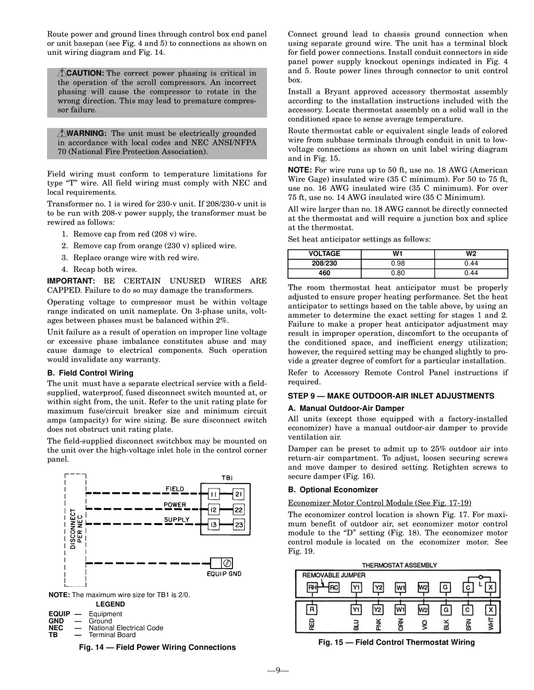
Route power and ground lines through control box end panel or unit basepan (see Fig. 4 and 5) to connections as shown on unit wiring diagram and Fig. 14.

CAUTION: The correct power phasing is critical in the operation of the scroll compressors. An incorrect phasing will cause the compressor to rotate in the wrong direction. This may lead to premature compres- sor failure.

WARNING: The unit must be electrically grounded in accordance with local codes and NEC ANSI/NFPA 70 (National Fire Protection Association).

Field wiring must conform to temperature limitations for type “T” wire. All field wiring must comply with NEC and local requirements.

Transformer no. 1 is wired for 230-v unit. If 208/230-v unit is to be run with 208-v power supply, the transformer must be rewired as follows:

1.Remove cap from red (208 v) wire.

2.Remove cap from orange (230 v) spliced wire.

3.Replace orange wire with red wire.

4.Recap both wires.

IMPORTANT: BE CERTAIN UNUSED WIRES ARE CAPPED. Failure to do so may damage the transformers.

Operating voltage to compressor must be within voltage range indicated on unit nameplate. On 3-phase units, volt- ages between phases must be balanced within 2%.

Unit failure as a result of operation on improper line voltage or excessive phase imbalance constitutes abuse and may cause damage to electrical components. Such operation would invalidate any warranty.

B. Field Control Wiring

The unit must have a separate electrical service with a field- supplied, waterproof, fused disconnect switch mounted at, or within sight from, the unit. Refer to the unit rating plate for maximum fuse/circuit breaker size and minimum circuit amps (ampacity) for wire sizing. Be sure disconnect switch does not obstruct unit rating plate.

The field-supplied disconnect switchbox may be mounted on the unit over the high-voltage inlet hole in the control corner panel.

NOTE: The maximum wire size for TB1 is 2/0.

LEGEND

EQUIP — Equipment

GND — Ground

NEC — National Electrical Code

TB — Terminal Board

Fig. 14 — Field Power Wiring Connections

Connect ground lead to chassis ground connection when using separate ground wire. The unit has a terminal block for field power connections. Install conduit connectors in side panel power supply knockout openings indicated in Fig. 4 and 5. Route power lines through connector to unit control box.

Install a Bryant approved accessory thermostat assembly according to the installation instructions included with the accessory. Locate thermostat assembly on a solid wall in the conditioned space to sense average temperature.

Route thermostat cable or equivalent single leads of colored wire from subbase terminals through conduit in unit to low- voltage connections as shown on unit label wiring diagram and in Fig. 15.

NOTE: For wire runs up to 50 ft, use no. 18 AWG (American Wire Gage) insulated wire (35 C minimum). For 50 to 75 ft, use no. 16 AWG insulated wire (35 C minimum). For over 75 ft, use no. 14 AWG insulated wire (35 C Minimum).

All wire larger than no. 18 AWG cannot be directly connected at the thermostat and will require a junction box and splice at the thermostat.

Set heat anticipator settings as follows:

VOLTAGE

W1

W2

208/230

0.98

0.44

460

0.80

0.44

The room thermostat heat anticipator must be properly adjusted to ensure proper heating performance. Set the heat anticipator to settings based on the table above, by using an ammeter to determine the exact setting for stages 1 and 2. Failure to make a proper heat anticipator adjustment may result in improper operation, discomfort to the occupants of the conditioned space, and inefficient energy utilization; however, the required setting may be changed slightly to pro- vide a greater degree of comfort for a particular installation.

Refer to Accessory Remote Control Panel instructions if required.

STEP 9 — MAKE OUTDOOR-AIR INLET ADJUSTMENTS

A. Manual Outdoor-Air Damper

All units (except those equipped with a factory-installed economizer) have a manual outdoor-air damper to provide ventilation air.

Damper can be preset to admit up to 25% outdoor air into return-air compartment. To adjust, loosen securing screws and move damper to desired setting. Retighten screws to secure damper (Fig. 16).

B. Optional Economizer

Economizer Motor Control Module (See Fig. 17-19)

The economizer control location is shown Fig. 17. For maxi- mum benefit of outdoor air, set economizer motor control module to the “D” setting (Fig. 18). The economizer motor control module is located on the economizer motor. See Fig. 19.

Fig. 15 — Field Control Thermostat Wiring

—9—

Page 9
Image 9
Bryant 581A Field Control Wiring, Make OUTDOOR-AIR Inlet Adjustments, Manual Outdoor-Air Damper, Optional Economizer

581A specifications

The Bryant 581A is a pivotal model in the realm of heating, ventilation, and air conditioning (HVAC) systems, known for its robust performance and energy efficiency. As part of the Bryant product lineup, the 581A offers a blend of innovative technologies combined with reliable engineering, making it a suitable choice for both residential and light commercial applications.

One of the standout features of the Bryant 581A is its outstanding energy efficiency. With a Seasonal Energy Efficiency Ratio (SEER) rating of up to 16, this model meets Energy Star qualifications, ensuring that homeowners can enjoy lower utility bills while helping to reduce their environmental footprint. The efficiency is further enhanced by the unit’s environmentally friendly refrigerant, which not only improves performance but also aligns with modern sustainability standards.

Another key characteristic of the Bryant 581A is its durable construction. Designed to withstand various weather conditions, the unit features a robust cabinet that protects internal components. This durability not only prolongs the lifespan of the system but also minimizes the need for frequent maintenance or repairs. The coil design is optimized for heat transfer efficiency, enhancing the unit's overall performance in both cooling and heating modes.

In terms of technology, the Bryant 581A incorporates advanced control systems that enable precise temperature regulation. The multi-stage cooling capabilities ensure that the system can adapt to varying temperature demands, providing comfort in all seasons. Additionally, the model is compatible with smart thermostats, allowing homeowners to control their HVAC system remotely via smartphone or other connected devices.

Noise reduction is another aspect where the Bryant 581A excels. Equipped with a variable-speed compressor and sound-dampening features, this model operates quietly, minimizing disruption in residential or office environments. This focus on acoustic comfort makes it an ideal choice for those who value a peaceful living or working space.

Overall, the Bryant 581A represents an excellent balance of efficiency, durability, and modern technology. With features aimed at enhancing user comfort and reducing operational costs, it stands out as a reliable solution in the competitive HVAC market. Whether for new installations or replacements, the Bryant 581A is a testament to the brand’s commitment to quality and innovation in home climate control.