D.Install Canopy.
1.Install ½" thick x 1" wide ceramic fiber gasket. See
Figure 7.
Figure 7: Canopy Gasket Installation
2.Position canopy on ceramic fiber gasket. See Figure
8.
Figure 8: Canopy Installation
3.Attach canopy using ¼" carriage bolts, nuts, and washers provided.
E.Inspect joints between sections. They were factory sealed. If there are any openings due to shipment or handling, reseal with boiler putty.
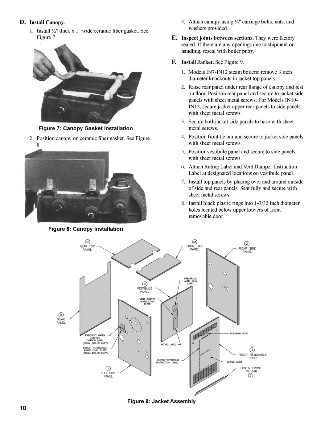
F.Install Jacket. See Figure 9.
1.Models
2.Raise rear panel under rear flange of canopy and rest on floor. Position rear panel and secure to jacket side panels with sheet metal screws. For Models IN10- IN12, secure jacket upper rear panels to side panels with sheet metal screws.
3.Secure both jacket side panels to base with sheet metal screws.
4.Position front tie bar and secure to jacket side panels with sheet metal screws.
5.Position vestibule panel and secure to side panels with sheet metal screws.
6.Attach Rating Label and Vent Damper Instruction Label at designated locations on vestibule panel.
7.Install top panels by placing over and around outside of side and rear panels. Seat fully and secure with sheet metal screws.
8.Install black plastic rings into
Figure 9: Jacket Assembly
10