Key | Description | Part No. |
|
|
|
| Quantity |
|
|
|
| ||
|
|
|
|
|
|
|
|
|
|
| |||
No. | IN3 | IN4 | IN5 | IN6 | IN7 | IN8 |
| IN9 | IN10 | IN11 | IN12 | ||
|
|
| |||||||||||
|
|
|
| ||||||||||
|
|
|
|
|
|
|
|
|
|
|
|
|
|
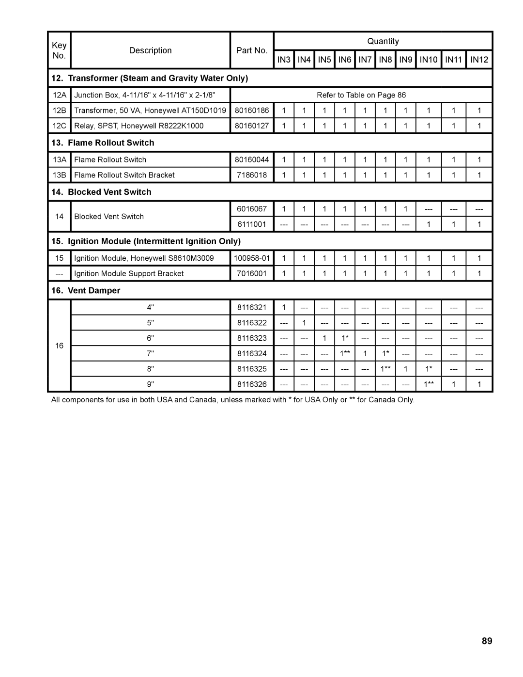
12. Transformer (Steam and Gravity Water Only) |
|
|
|
|
|
|
|
|
|
|
| ||
|
|
|
|
|
|
|
| ||||||
12A | Junction Box, |
|
|
| Refer to Table on Page 86 |
|
|
| |||||
|
|
|
|
|
|
|
|
|
|
|
|
|
|
12B | Transformer, 50 VA, Honeywell AT150D1019 | 80160186 | 1 | 1 | 1 | 1 | 1 | 1 |
| 1 | 1 | 1 | 1 |
|
|
|
|
|
|
|
|
|
|
|
|
|
|
12C | Relay, SPST, Honeywell R8222K1000 | 80160127 | 1 | 1 | 1 | 1 | 1 | 1 |
| 1 | 1 | 1 | 1 |
|
|
|
|
|
|
|
|
|
|
|
|
|
|
13. Flame Rollout Switch |
|
|
|
|
|
|
|
|
|
|
|
| |
|
|
|
|
|
|
|
|
|
|
|
|
|
|
13A | Flame Rollout Switch | 80160044 | 1 | 1 | 1 | 1 | 1 | 1 |
| 1 | 1 | 1 | 1 |
|
|
|
|
|
|
|
|
|
|
|
|
|
|
13B | Flame Rollout Switch Bracket | 7186018 | 1 | 1 | 1 | 1 | 1 | 1 |
| 1 | 1 | 1 | 1 |
|
|
|
|
|
|
|
|
|
|
|
|
|
|
14. Blocked Vent Switch |
|
|
|
|
|
|
|
|
|
|
|
| |
|
|
|
|
|
|
|
|
|
|
|
|
|
|
14 | Blocked Vent Switch | 6016067 | 1 | 1 | 1 | 1 | 1 | 1 |
| 1 | |||
|
|
|
|
|
|
|
|
|
|
|
| ||
6111001 |
| 1 | 1 | 1 | |||||||||
|
|
| |||||||||||
|
|
|
|
|
|
|
|
|
|
|
|
|
|
15. Ignition Module (Intermittent Ignition Only) |
|
|
|
|
|
|
|
|
|
|
| ||
|
|
|
|
|
|
|
|
|
|
|
|
| |
15 | Ignition Module, Honeywell S8610M3009 | 1 | 1 | 1 | 1 | 1 | 1 |
| 1 | 1 | 1 | 1 | |
|
|
|
|
|
|
|
|
|
|
|
|
|
|
Ignition Module Support Bracket | 7016001 | 1 | 1 | 1 | 1 | 1 | 1 |
| 1 | 1 | 1 | 1 | |
|
|
|
|
|
|
|
|
|
|
|
|
|
|
16. Vent Damper |
|
|
|
|
|
|
|
|
|
|
|
| |
|
|
|
|
|
|
|
|
|
|
|
|
|
|
| 4" | 8116321 | 1 |
| |||||||||
|
|
|
|
|
|
|
|
|
|
|
|
|
|
| 5" | 8116322 | 1 |
| |||||||||
|
|
|
|
|
|
|
|
|
|
|
|
|
|
16 | 6" | 8116323 | 1 | 1* |
| ||||||||
|
|
|
|
|
|
|
|
|
|
|
|
| |
7" | 8116324 | 1** | 1 | 1* |
| ||||||||
|
| ||||||||||||
|
|
|
|
|
|
|
|
|
|
|
|
|
|
| 8" | 8116325 | 1** |
| 1 | 1* | |||||||
|
|
|
|
|
|
|
|
|
|
|
|
|
|
| 9" | 8116326 |
| 1** | 1 | 1 | |||||||
|
|
|
|
|
|
|
|
|
|
|
|
|
|
All components for use in both USA and Canada, unless marked with * for USA Only or ** for Canada Only.
89