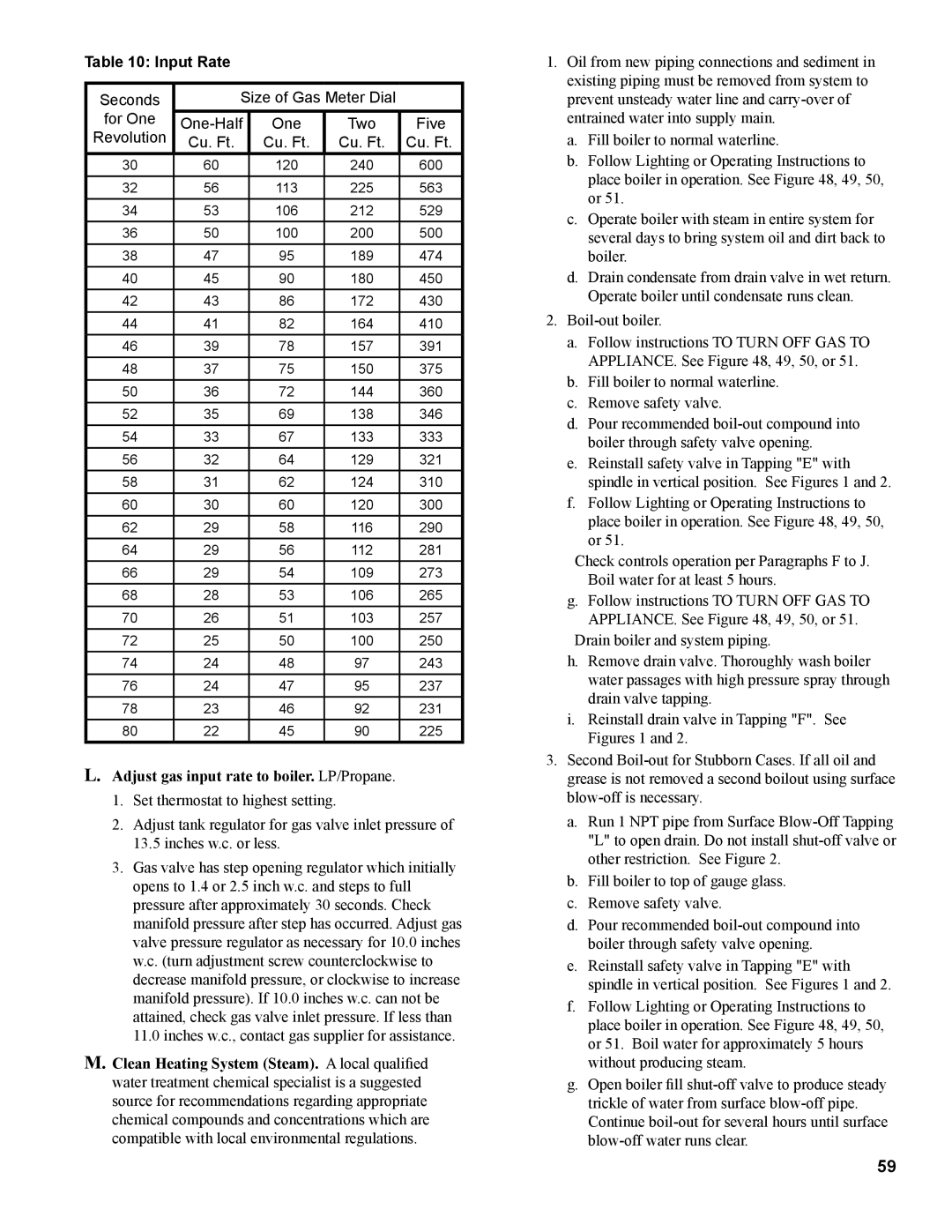
Table 10: Input Rate
Seconds | Size of Gas Meter Dial |
| ||
for One | One | Two | Five | |
Revolution | Cu. Ft. | Cu. Ft. | Cu. Ft. | Cu. Ft. |
30 | 60 | 120 | 240 | 600 |
32 | 56 | 113 | 225 | 563 |
34 | 53 | 106 | 212 | 529 |
36 | 50 | 100 | 200 | 500 |
38 | 47 | 95 | 189 | 474 |
40 | 45 | 90 | 180 | 450 |
42 | 43 | 86 | 172 | 430 |
44 | 41 | 82 | 164 | 410 |
46 | 39 | 78 | 157 | 391 |
48 | 37 | 75 | 150 | 375 |
50 | 36 | 72 | 144 | 360 |
52 | 35 | 69 | 138 | 346 |
54 | 33 | 67 | 133 | 333 |
56 | 32 | 64 | 129 | 321 |
58 | 31 | 62 | 124 | 310 |
60 | 30 | 60 | 120 | 300 |
62 | 29 | 58 | 116 | 290 |
64 | 29 | 56 | 112 | 281 |
66 | 29 | 54 | 109 | 273 |
68 | 28 | 53 | 106 | 265 |
70 | 26 | 51 | 103 | 257 |
72 | 25 | 50 | 100 | 250 |
74 | 24 | 48 | 97 | 243 |
76 | 24 | 47 | 95 | 237 |
78 | 23 | 46 | 92 | 231 |
80 | 22 | 45 | 90 | 225 |
L.Adjust gas input rate to boiler. LP/Propane.
1.Set thermostat to highest setting.
2.Adjust tank regulator for gas valve inlet pressure of
13.5inches w.c. or less.
3.Gas valve has step opening regulator which initially opens to 1.4 or 2.5 inch w.c. and steps to full pressure after approximately 30 seconds. Check manifold pressure after step has occurred. Adjust gas valve pressure regulator as necessary for 10.0 inches w.c. (turn adjustment screw counterclockwise to decrease manifold pressure, or clockwise to increase manifold pressure). If 10.0 inches w.c. can not be attained, check gas valve inlet pressure. If less than
11.0inches w.c., contact gas supplier for assistance.
M.Clean Heating System (Steam). A local qualified water treatment chemical specialist is a suggested source for recommendations regarding appropriate chemical compounds and concentrations which are compatible with local environmental regulations.
1.Oil from new piping connections and sediment in existing piping must be removed from system to prevent unsteady water line and
a.Fill boiler to normal waterline.
b.Follow Lighting or Operating Instructions to place boiler in operation. See Figure 48, 49, 50, or 51.
c.Operate boiler with steam in entire system for several days to bring system oil and dirt back to boiler.
d.Drain condensate from drain valve in wet return. Operate boiler until condensate runs clean.
2.
a.Follow instructions TO TURN OFF GAS TO APPLIANCE. See Figure 48, 49, 50, or 51.
b.Fill boiler to normal waterline.
c.Remove safety valve.
d.Pour recommended
e.Reinstall safety valve in Tapping "E" with spindle in vertical position. See Figures 1 and 2.
f.Follow Lighting or Operating Instructions to place boiler in operation. See Figure 48, 49, 50, or 51.
Check controls operation per Paragraphs F to J. Boil water for at least 5 hours.
g.Follow instructions TO TURN OFF GAS TO APPLIANCE. See Figure 48, 49, 50, or 51.
Drain boiler and system piping.
h.Remove drain valve. Thoroughly wash boiler water passages with high pressure spray through drain valve tapping.
i.Reinstall drain valve in Tapping "F". See Figures 1 and 2.
3.Second
a.Run 1 NPT pipe from Surface
b.Fill boiler to top of gauge glass.
c.Remove safety valve.
d.Pour recommended
e.Reinstall safety valve in Tapping "E" with spindle in vertical position. See Figures 1 and 2.
f.Follow Lighting or Operating Instructions to place boiler in operation. See Figure 48, 49, 50, or 51. Boil water for approximately 5 hours without producing steam.
g.Open boiler fill
59