Set heat anticipator to match system requirements. See Table 6. In general, setting heat anticipator too low will cause boiler to short cycle without bringing heated space up to temperature. Setting heat anticipator too high will allow boiler to operate longer than necessary and overheat space.
D.Wire thermostat. Provide Class II circuit between thermostat and boiler.
1.Steam or Water with gravity circulation or tankless heater. Remove transformer from junction box. Connect one wire from thermostat to blue wire(s). Connect additional wire from thermostat to brown wire or red wire for water with tankless heater.
2.Water with intermittent circulation and without tankless heater. Connect one wire from thermostat to Terminal "T" and additional wire to terminal "TV".
E.Alliance Indirect Water Heater (if used).
1.For wiring refer to wiring diagrams located in this section and Alliance Installation Operating and Service Instructions.
2.Attach junction box extension (4 - 11/16 square) to junction box on boiler.
3.Steam Boilers only. Verify temperature limit (Honeywell L4006 or equal, which is installer supplied) is installed in Tapping "P", refer to Section V: Piping and Trim.
F.Wire control circuit as shown in the appropriate wiring diagram. See Table 6.
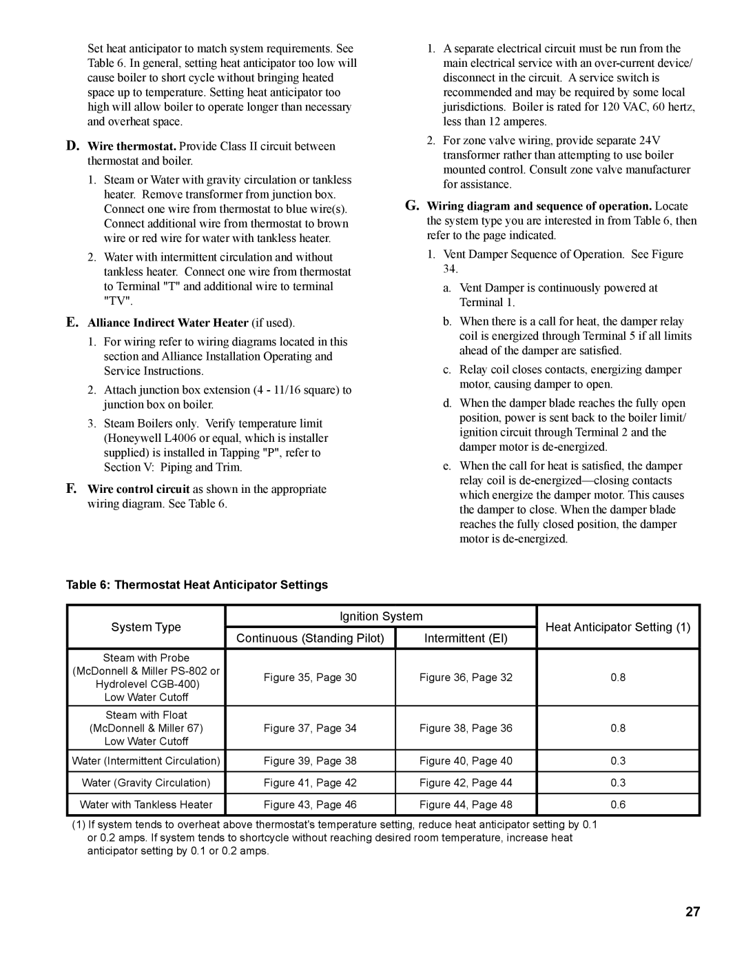
Table 6: Thermostat Heat Anticipator Settings
1.A separate electrical circuit must be run from the main electrical service with an
2.For zone valve wiring, provide separate 24V transformer rather than attempting to use boiler mounted control. Consult zone valve manufacturer for assistance.
G.Wiring diagram and sequence of operation. Locate the system type you are interested in from Table 6, then refer to the page indicated.
1.Vent Damper Sequence of Operation. See Figure 34.
a.Vent Damper is continuously powered at Terminal 1.
b.When there is a call for heat, the damper relay coil is energized through Terminal 5 if all limits ahead of the damper are satisfied.
c.Relay coil closes contacts, energizing damper motor, causing damper to open.
d.When the damper blade reaches the fully open position, power is sent back to the boiler limit/ ignition circuit through Terminal 2 and the damper motor is
e.When the call for heat is satisfied, the damper relay coil is
System Type | Ignition System | Heat Anticipator Setting (1) | ||
|
| |||
Continuous (Standing Pilot) | Intermittent (EI) | |||
|
| |||
|
|
|
| |
Steam with Probe |
|
|
| |
(McDonnell & Miller | Figure 35, Page 30 | Figure 36, Page 32 | 0.8 | |
Hydrolevel | ||||
|
|
| ||
Low Water Cutoff |
|
|
| |
Steam with Float |
|
|
| |
(McDonnell & Miller 67) | Figure 37, Page 34 | Figure 38, Page 36 | 0.8 | |
Low Water Cutoff |
|
|
| |
Water (Intermittent Circulation) | Figure 39, Page 38 | Figure 40, Page 40 | 0.3 | |
|
|
|
| |
Water (Gravity Circulation) | Figure 41, Page 42 | Figure 42, Page 44 | 0.3 | |
|
|
|
| |
Water with Tankless Heater | Figure 43, Page 46 | Figure 44, Page 48 | 0.6 | |
|
|
|
| |
(1)If system tends to overheat above thermostat's temperature setting, reduce heat anticipator setting by 0.1 or 0.2 amps. If system tends to shortcycle without reaching desired room temperature, increase heat anticipator setting by 0.1 or 0.2 amps.
27