3.All Steam Boilers and Water Boilers except "EZW" and "WC" Controls Cartons
a.Install Junction Box. See Figure 19A.
i. Remove center knockout in rear of Junction
Box and insert black plastic snap bushing in hole.
ii. Install mounting bracket to rear of Junction
Box with two (2) blunt sheet metal screws provided.
iii. Align center and mounting holes of Junction
Box with upper front corner of jacket left side panel.
iv. Install Junction Box to jacket from inside vestibule area with two (2) blunt sheet metal screws provided.
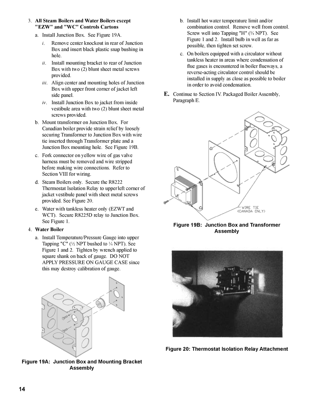
b.Mount transformer on Junction Box. For
Canadian boiler provide strain relief by loosely securing Transformer to Junction Box with wire tie inserted through Transformer plate and a
Junction Box mounting hole. See Figure 19B.
c.Fork connector on yellow wire of gas valve harness must be removed and wire stripped before making wire connections. Refer to Section VIII for wiring.
d.Steam Boilers only. Secure the R8222 Thermostat Isolation Relay to upper left corner of jacket vestibule panel with sheet metal screws provided. See Figure 20.
e.Water with tankless heater only (EZWT and
WCT). Secure R8225D relay to Junction Box.
See Figure 1.
4.Water Boiler
a.Install Temperature/Pressure Gauge into upper Tapping "C" (½ NPT bushed to ¼ NPT). See Figure 1 and 2. Tighten by wrench applied to square shank on back of gauge. DO NOT APPLY PRESSURE ON GAUGE CASE since this may destroy calibration of gauge.
Figure 19A: Junction Box and Mounting Bracket
Assembly
b.Install hot water temperature limit and/or combination control. Remove well from control. Screw well into Tapping "H" (¾ NPT). See Figure 1 and 2. Install bulb in well as far as possible, then tighten set screw.
c.On boilers equipped with a circulator without tankless heater in areas where condensation of flue gases is encountered in boiler flueways, a
E.Continue to Section IV. Packaged Boiler Assembly, Paragraph E.
Figure 19B: Junction Box and Transformer
Assembly
Figure 20: Thermostat Isolation Relay Attachment
14