Manuals
/
Burnham
/
Household Appliance
/
Boiler
Burnham
IN10
manual
Dimensional Drawing
Models:
IN10
1
4
92
92
Download
92 pages
62.26 Kb
1
2
3
4
5
6
7
8
Install
XI. Repair Parts
Wire Vent Damper if used
Warranty
Dimension
III. Semi-Pak Boiler Assembly
Boiler Flueway Cleaning
Service Instructions
Flame Rollout Switch
Page 4
Image 4
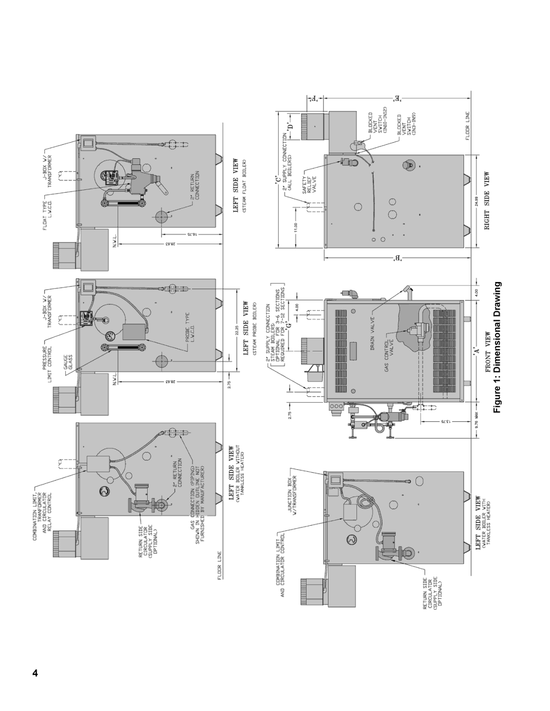
Figure 1: Dimensional Drawing
Page 3
Page 5
Page 4
Image 4
Page 3
Page 5
Contents
Independence
8141049R26-10/08 Price $5.00
Page
Page
Dimensional Drawing
Table of Contents
Probe L.W.C.O Float L.W.C.O Tankless Heater
Pre-Installation
Clearance to Combustible Materials
Install Base-Burner-Manifold Assembly
II. Knocked-Down Boiler Assembly
Install assembled cast iron sections on base assembly
Install Canopy
Canopy Gasket Installation
Combustion Chamber
Install Blocked Vent Switch with sheet metal screws
Intermittent Ignition EI Install Ignition Module
III. Semi-Pak Boiler Assembly
Install Trim and Controls
Remove Crate
Steam Boiler with Probe Low Water Cutoff
Junction Box and Mounting Bracket Assembly
Water Boiler
Install Jacket Front Panel
IV. Packaged Boiler Assembly
Remove Jacket Front Panel. See Figure
Piping and Trim
Page
Recommended Water Piping for Circulator Zoned Heating System
Recommended Water Piping for Zone Valve Zoned Heating System
Recommended Piping for Indirect Water Heater
Page
Rated Input
VI. Gas Piping
Connect boiler gas valve to gas supply system
Fitting Equivalent Lengths
Specific Gravity Correction Factors for Natural Gas
VII. Venting
Boiler Equipped With Vent Damper
Typical Vent Installation
If an Existing Boiler is Removed
Wire Vent Damper if used
VIII. Electrical
Thermostat Heat Anticipator Settings
Alliance Indirect Water Heater if used
Vent Damper Harness to Limit
This page Left Intentionally Blank
Page
Page
Page
Page
Page
Page
Page
Page
Page
Page
Page
Page
Page
Page
Page
Page
Page
Page
Page
Page
IX. System Start-up
Fill boiler with water
Prepare to check operation
Follow Lighting or Operating Instructions
Page
Page
Page
Page
Ignition Module Wiring Ladder Diagram Terminal Designation
Ignition Module Terminal Cross-Reference
Green LED Status Codes
OFF
Pilot Burner Flame, Honeywell Q350
Adjust gas input rate to boiler. Natural Gas
Check low water cutoff steam only
Do not drain below gauge glass
Check Limit
Adjust gas input rate to boiler. LP/Propane
Input Rate
Page
Page
Service Instructions
Maintenance of Low Water Cutoff
Boiler Flueway Cleaning
Clean Boiler Flueways
Pilot Burner Location
Tankless Heater
Excessive Make-Up Water
Model No Gallons Per Month Year
Honeywell Electronic Ignition Trouble Shooting Guide
Honeywell Hot Surface to Pilot Trouble Shooting Guide
Avoid Breathing Fiber Particulates and Dust
XI. Repair Parts
Service Record
Section Assembly
Canopy and Draft Hood Canopy/Draft Hood Parts
Base Assembly
Base Tray
Burner Tray 1 Inch Main Burners
Manifold and 1 Main Burners
Manifold and Main Burners 1 Inch Main Burners Only
Manifold and 40mm Main Burners
Manifold and Main Burners 40MM Main Burners only
Intermittent Ignition Only
Volt Continuous Ignition Standing Pilot Natural Gas
LP Gas, High Altitude 2000-5000 Ft. USA Only
Natural Gas, High Altitude 5000-9000 Ft. USA Only
LP Gas, High Altitude 5000-9000 Ft. USA Only
Natural Gas, High Altitude 2000-4500 Ft. Canada Only
Pilot Burner, Honeywell Q350A1321
Pilot Burner, Honeywell Q348A1002
Page
Jacket Assembly
Jacket Assembly Refer to Figure on
Front Top Panel
Steam Trim
Page
Water Trim
Quantity
This page Left Blank Intentionally
Page
Flame Rollout Switch
Blocked Vent Switch
Transformer Steam and Gravity Water Only
Ignition Module Intermittent Ignition Only
XII. Low Water Cut Off Lwco
Wiring of Typical Lwco
Lwco Location
Limited Warranty
Limited Warranty
Top
Page
Image
Contents