REMOTE HOSES SUPPORT
After installing loader onto tractor, raise the loader to full height, stop engine, lock brakes, and remove key. Then gather remote hoses and install nylon tie through hose support hole located in right hand loader subframe. Secure hoses as shown. This will allow remote hoses to be supported by loader frame instead of loader steel tubing. Refer to Figure 5.
![]() CAUTION
CAUTION ![]()
DO NOT STAND, WALK OR WORK UNDER A RAISED LOADER OR ATTACHMENT UNLESS IT IS SECURELY BLOCKED OR HELD IN POSITION. ACCIDENTAL MOVE- MENT OF A CONTROL LEVER/LEVERS OR LEAKS IN THE HYDRAULIC SYSTEM COULD CAUSE THE LOADER TO DROP, OR ATTACHMENT TO DUMP, CAUSING SEVERE INJURY.
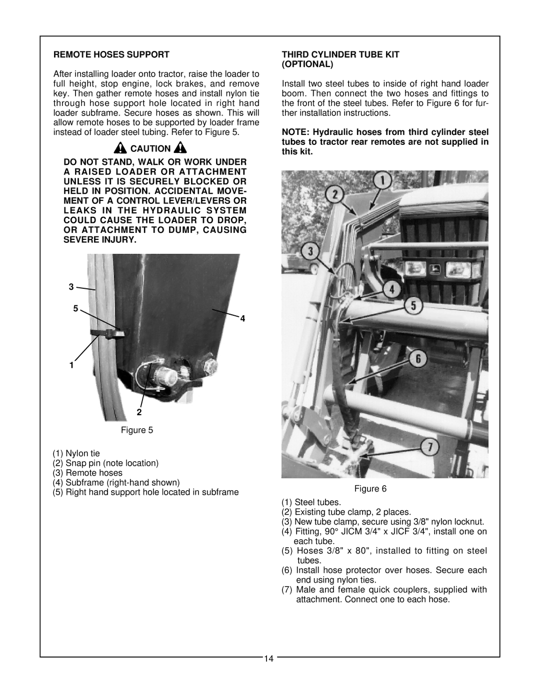
THIRD CYLINDER TUBE KIT (OPTIONAL)
Install two steel tubes to inside of right hand loader boom. Then connect the two hoses and fittings to the front of the steel tubes. Refer to Figure 6 for fur- ther installation instructions.
NOTE: Hydraulic hoses from third cylinder steel tubes to tractor rear remotes are not supplied in this kit.
3
5
4
1
| 2 |
|
|
|
|
|
| |
|
|
|
|
|
|
|
|
|
|
| Figure 5 |
|
|
|
|
| |
|
|
|
|
|
|
|
|
|
|
|
|
|
|
|
|
|
|
(1) | Nylon tie |
|
|
|
|
| ||
(2) | Snap pin (note location) |
|
|
|
|
| ||
(3) | Remote hoses |
|
|
|
|
| ||
(4) | Subframe |
|
|
|
|
| ||
|
|
| Figure 6 |
| ||||
(5) | Right hand support hole located in subframe |
|
|
|
| |||
|
|
|
|
|
|
| ||
|
|
|
| (1) | Steel tubes. | |||
|
|
|
|
| (2) | Existing tube clamp, 2 places. | ||
|
|
|
|
| (3) New tube clamp, secure using 3/8" nylon locknut. | |||
|
|
|
|
| (4) | Fitting, 90° JICM 3/4" x JICF 3/4", install one on | ||
|
|
|
|
|
| each tube. | ||
|
|
|
|
| (5) Hoses 3/8" x 80", installed to fitting on steel | |||
|
|
|
|
|
| tubes. | ||
|
|
|
|
| (6) | Install hose protector over hoses. Secure each | ||
|
|
|
|
|
| end using nylon ties. | ||
|
|
|
|
| (7) | Male and female quick couplers, supplied with | ||
|
|
|
|
|
| attachment. Connect one to each hose. | ||
|
|
|
|
|
| |||
|
|
|
|
|
|
|
|
|
14
