QUICK DRAW BUCKET ONLY: Loosely secure plastic hose clamp and bar support with 3/8" flat- washer and nylon lock nut to 3/8" stud located on back side of bucket.
Locate center top of bucket and measure right 10 inches. Locate quick coupler mount on bucket at this point. Center punch and drill 7/16" diameter hole through top box section of bucket. Refer to Figure 9 and to Figure 6, page 37.
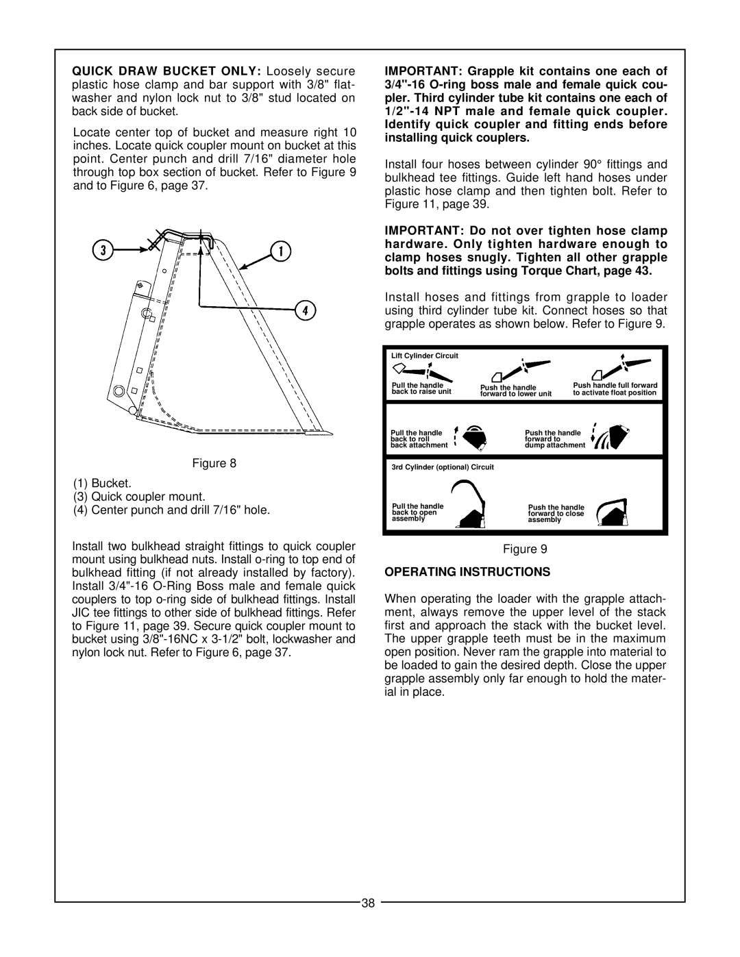
Figure 8
(1) Bucket.
(3)Quick coupler mount.
(4)Center punch and drill 7/16" hole.
Install two bulkhead straight fittings to quick coupler mount using bulkhead nuts. Install
IMPORTANT: Grapple kit contains one each of
Install four hoses between cylinder 90° fittings and bulkhead tee fittings. Guide left hand hoses under plastic hose clamp and then tighten bolt. Refer to Figure 11, page 39.
IMPORTANT: Do not over tighten hose clamp hardware. Only tighten hardware enough to clamp hoses snugly. Tighten all other grapple bolts and fittings using Torque Chart, page 43.
Install hoses and fittings from grapple to loader using third cylinder tube kit. Connect hoses so that grapple operates as shown below. Refer to Figure 9.
| Lift Cylinder Circuit |
|
|
|
|
|
|
| ||
| Pull the handle | Push the handle | Push handle full forward | |||||||
| back to raise unit | to activate float position | ||||||||
| forward to lower unit | |||||||||
|
|
|
|
|
|
|
|
|
| |
Pull the handle | Push the handle | |||||||||
back to roll |
|
|
| forward to |
|
|
| |||
back attachment |
|
|
| dump attachment |
|
| ||||
|
|
|
|
|
|
|
| |||
| 3rd Cylinder (optional) Circuit |
|
|
| ||||||
|
|
|
|
|
|
|
| |||
|
|
|
|
|
|
|
| |||
| Pull the handle |
|
|
|
|
| ||||
|
|
|
|
|
| Push the handle | ||||
| back to open |
|
|
|
| forward to close |
| |||
| assembly |
|
|
|
| assembly |
|
|
| |
|
|
|
|
|
|
|
|
|
|
|
Figure 9
OPERATING INSTRUCTIONS
When operating the loader with the grapple attach- ment, always remove the upper level of the stack first and approach the stack with the bucket level. The upper grapple teeth must be in the maximum open position. Never ram the grapple into material to be loaded to gain the desired depth. Close the upper grapple assembly only far enough to hold the mater- ial in place.
38