SmartSwitch 9A100 User Guide
SmartSwitch 9A100 User Guide
FCC Class a Notice
Declaration of Conformity Addendum
Safety Information Class 1 Laser Transceivers
Fiber Optic Protective Caps
Regulatory Compliance Summary Safety
Revision History
Table of Contents
Specifications
Acronyms Index
Xii SmartSwitch 9A100 User Guide
List of Figures
List of Figures Xiv SmartSwitch 9A100 User Guide
List of Tables
List of Tables Xvi SmartSwitch 9A100 User Guide
Introduction
Introduction SmartSwitch 9A100 User Guide
Unpacking the Switch
Switch Installation and Setup
Check Accessory Carton Contents
Inspecting the Switch
SmartSwitch 9A100-04 front panel
1 DS3 and E3 I/O Module Configuration
Installing the Switch
Installing the SmartSwitch 9A100
Configuring the Switch
SmartSwitch 9A100 console and network connections
Using the Console
Console Commands
SmartSwitch # show portconfig a1
Creating an Alias
SmartSwitch # set consoletimeout
Console Time-out
Traffic
Ambiguous Commands
SwitchTrafficCongestion. For example
Console Help
Smartswitch ATM Administrator
SmartSwitch # ? add laneclient
Exterior
SmartSwitch ATM Administrator
Installation Steps
MB RAM
Accessing Online Help
Starting SmartSwitch ATM Administrator the First Time
User Name Access Level Default Password
SmartSwitch ATM Administrator
IP Over ATM and Lane
SmartSwitch # add ipatmclient
Creating AN IP Over ATM Vlan
Server Is local Server Connection Established
ATM Addressing for IP over ATM
Creating AN Emulated LAN
3900000000000000000014418000005A01010100
Add Elan
No Lane server address is specified see note below
Ilmi
ELANs Across Multiple Switches
ATM Addressing for LAN Emulation
SmartSwitch# add laneclient
Switch Clients
Elan1
Page
Backing UP and Restoring Switch Configuration
Switch Administration
Path /backdir/config-1
ATM Routing
SmartSwitch# restore switch
SmartSwitch # show netprefix b2
Creating an Iisp Route
AtmAddress
Atmroute
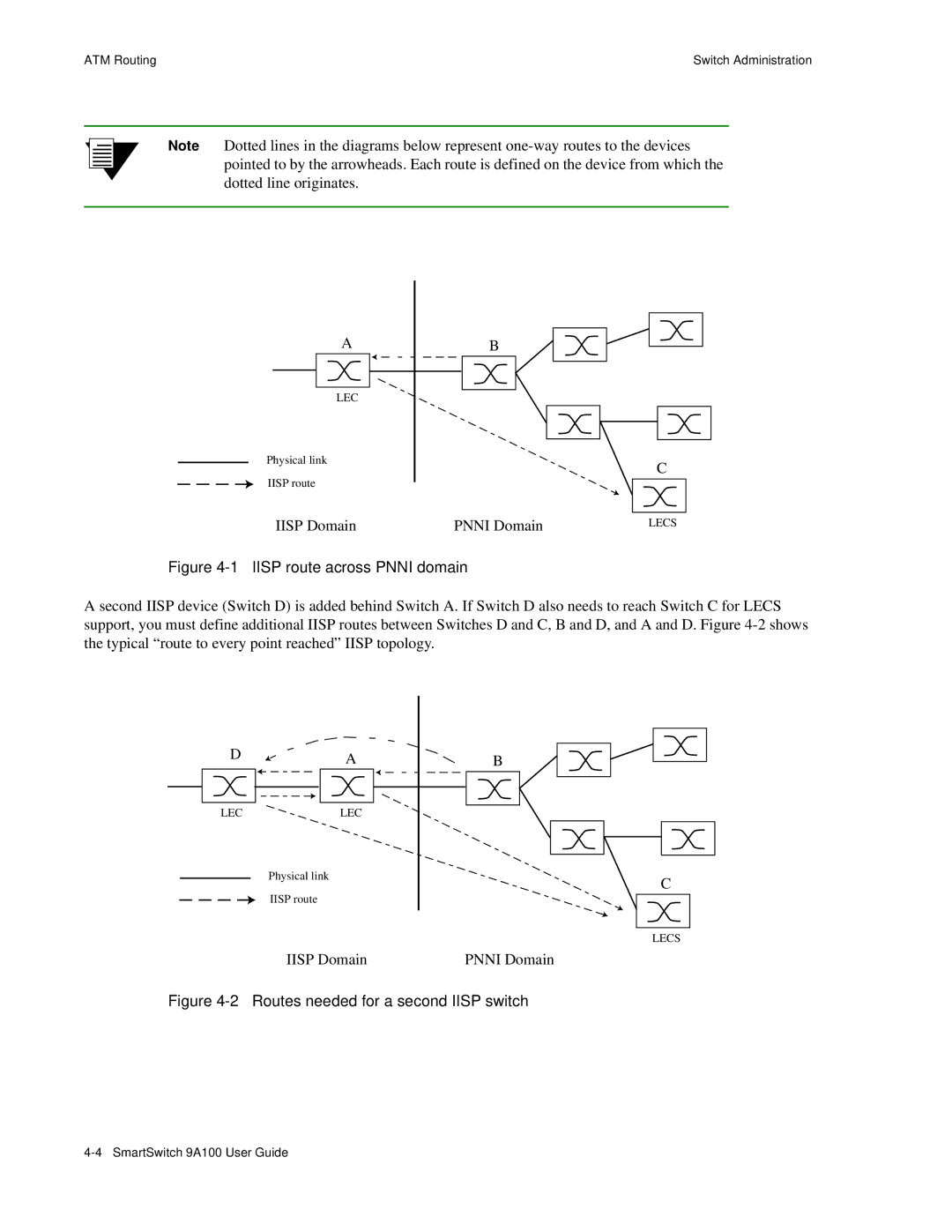
Iisp route across Pnni domain
UNI Routes
Route Metrics
SmartSwitch # show pnnimetrics
IP Routing
90.1.1.254
Route NET Table
Events and Alarms
Event Categories
Viewing Events and Alarms
SmartSwitch # set eventdisplay
SmartSwitch # set alarmdisplay
Deleting Events and Alarms
PVC Connections
Point-to-Point PVCs
SmartSwitch # add trafficdescriptor
SmartSwitch # show trafficdescriptor
100
Point-to-Multipoint PVCs
Md1 #add trafficdescriptor
Local
Connecting to Local Switch Client Through a PVC
10.1.1.0
Non-zero VPIs
VCC Mask Index VPI Bits VPI Values VCI Bits VCI Values
Use show portconfig to see the change to port A1
SmartSwitch # set portconfig a1
Traffic Management
Traffic Descriptors
Type Number Descriptor Characteristics
Traffic Descriptor with CLP and best effort
8000
Call Admission Control Policy
5000
Ubr
SmartSwitch # set porttrafficcongestion
Min for CBR queue
SmartSwitch # show switchtrafficcongestion
QoS Queue Recommended Settings
EFCI, EPD, and RM Thresholds
Accessing the Boot Load Prompt
Upgrading and Changing Software
Boot Load Commands
Command Action Parameters
Boot Prom
Upgrading Boot Load Software
Flash RAM
=df b
=chpi
Upgrading Post Diagnostic Software
=df p
Upgrading Switch Operating Software
=df s
SmartSwitch # update firmware
Using the Update Firmware Command
214.95.77.240
Saving Core Dumps
204.95.77.240
Tftpboot/bobr/core
Set CoreDump command
Bobr
Error IP e0103288 PFP e04be080 R0pfp e04be040 R1sp e04be0c0
Troubleshooting
Troubleshooting IP Over ATM
Troubleshooting LAN Emulation
Troubleshooting Pnni Links
Diagnosing Congestion
Troubleshooting Congestion
Global Congestion
Port Congestion
Troubleshooting Congestion
Appendix a Specifications
Function
Figure A-1 SmartSwitch 9A100 front panel
Specification Value
¢ %+2,%/˜96%,,%,329
Table A-4 ATM port specifications
Protocol Standard
Management Protocol Supported MIBs
RJ-45 Pin RJ-45 Color DB-9 Pin DB-9 Description
Technical Specifications
Appendix B Agent Support
MIB, SMI, MIB Files and Internet MIB Hierarchy
ZeitNet Cabletron Proprietary MIBs
MIB, SMI, MIB Files and Internet MIB Hierarchy
Relation Between Object Identifier and the Represented Value
Supported protocols
Supported SMI Formats
Zeitnet Cabletron Proprietary MIB Groups
Name Object Identifier Function
SmartSwitch 9A100 MIB Support
MIB Exceptions
Managing the SmartSwitch 9A100
Console Commands that Affect the Agent
Update firmware Backup Restore Reboot
Appendix C Technical Support
FAX Service
Electronic Services
Telephone Assistance
Software Warranty
Hardware Warranty
Repair Services
Appendix D Acronyms
Bootp
DTE
FCS
Ilmi
LES
Netbeui
PDU
RMA
SVC
VBR/RT
Acronyms SmartSwitch 9A100 User Guide
Index
Numerics
Elan
Lane
Snmp
Lane Pnni
Non-zero values