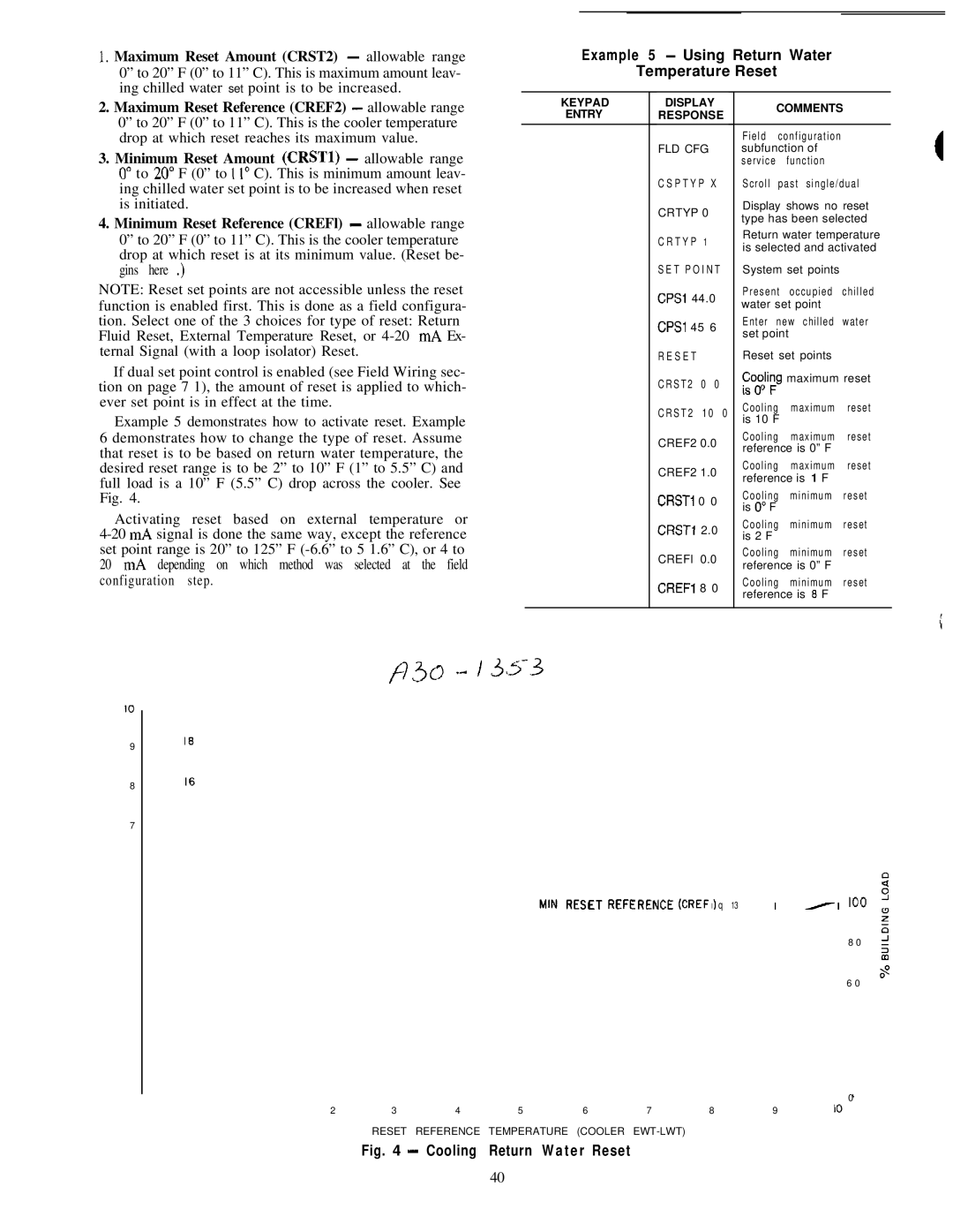
I. Maximum Reset Amount (CRST2) - allowable range 0” to 20” F (0” to 11” C). This is maximum amount leav- ing chilled water set point is to be increased.

2.Maximum Reset Reference (CREF2) - allowable range 0” to 20” F (0” to 11” C). This is the cooler temperature drop at which reset reaches its maximum value.

3.Minimum Reset Amount (CRSTl) - allowable range 0” to 20” F (0” to 1 I” C). This is minimum amount leav- ing chilled water set point is to be increased when reset is initiated.

4.Minimum Reset Reference (CREFl) - allowable range 0” to 20” F (0” to 11” C). This is the cooler temperature drop at which reset is at its minimum value. (Reset be- gins here .)

NOTE: Reset set points are not accessible unless the reset function is enabled first. This is done as a field configura- tion. Select one of the 3 choices for type of reset: Return Fluid Reset, External Temperature Reset, or 4-20 mA Ex- ternal Signal (with a loop isolator) Reset.

If dual set point control is enabled (see Field Wiring sec- tion on page 7 1), the amount of reset is applied to which- ever set point is in effect at the time.

Example 5 demonstrates how to activate reset. Example 6 demonstrates how to change the type of reset. Assume that reset is to be based on return water temperature, the desired reset range is to be 2” to 10” F (1” to 5.5” C) and full load is a 10” F (5.5” C) drop across the cooler. See Fig. 4.

Activating reset based on external temperature or 4-20 mA signal is done the same way, except the reference set point range is 20” to 125” F (-6.6” to 5 1.6” C), or 4 to 20 mA depending on which method was selected at the field configuration step.

Example 5 - Using Return Water

Temperature Reset


KEYPAD

DISPLAY


COMMENTS


ENTRY

RESPONSE


Field

configuration


FLD CFG


subfunction of


service


function


CSPTYP X

Scroll

past single/dual


CRTYP 0


Display shows no reset


type has been selected


CRTYP

1


Return water temperature


is selected and activated


SET POINT

System set points


CPSl 44.0

Present

occupied

chilled


water set point


CPSl 45 6

Enter

new chilled

water


set point


RESET


Reset set points


CRST2

0

0

F;li;g


maximum reset


0


CRST2

10

0

Cooling

maximum

reset


is 10 F


CREF2 0.0

Cooling

maximum

reset


reference is 0” F


CREF2 1.0

Cooling

maximum

reset


reference is 1 F


CRSTI

0 0

Cooling

minimum

reset


is 0” F


CRSTI 2.0

Cooling

minimum

reset


is 2 F


CREFl

0.0

Cooling

minimum

reset


reference is 0” F


CREFl

8 0

Cooling

minimum

reset


reference is 8 F


IO

9

8

7

f73c=) --/ 35.3

18

16

MIN RESET REFERENCE

(CREF I ) q 13

100

8 0

6 0

0

2

3

4

5

6

7

8

9

IO

RESET REFERENCE TEMPERATURE (COOLER EWT-LWT)

Fig. 4 - Cooling Return Water Reset

40

Page 40
Image 40
Carrier 040-420 specifications Example 5 Using Return Water Temperature Reset, Keypad Display Comments, CRST2, Crsti

040-420 specifications

The Carrier 040-420 is a highly regarded commercial HVAC unit specifically designed for efficient heating and cooling in medium- to large-sized buildings. Known for its reliability and advanced technology, this system is ideal for a variety of applications ranging from offices to industrial spaces.

One of the main features of the Carrier 040-420 is its energy efficiency. The unit utilizes advanced compressors and a high-efficiency heat exchanger, which work together to minimize energy consumption while maximizing performance. This is crucial in today’s energy-conscious environment, as businesses strive to reduce operational costs and their carbon footprint. The unit also boasts a high SEER (Seasonal Energy Efficiency Ratio) rating, making it an attractive option for those looking to lower their utility bills.

Equipped with advanced inverter-driven technology, the Carrier 040-420 allows for precise control of indoor climate conditions. This means that the system can adjust its output according to the actual cooling or heating demand of the space, resulting in enhanced comfort and reduced energy waste. The inverter technology also contributes to quieter operation, allowing for a more pleasant indoor environment.

Another feature that sets the Carrier 040-420 apart is its smart controls. The unit can be integrated with Carrier’s Building Automation Systems, enabling remote monitoring and management. This allows facility managers to optimize energy use and immediately respond to any performance issues. Additionally, the unit is compatible with various control interfaces, making it easy for users to adjust settings or schedule operations according to the building's occupancy patterns.

The robust design of the Carrier 040-420 ensures longevity and durability, even in harsh environmental conditions. Its weatherproof casing protects the internal components, enhancing the unit's performance and reliability over time. Maintenance is simplified with accessible design features, allowing technicians to conduct service checks and repairs without extensive downtime.

Overall, the Carrier 040-420 stands out as a modern HVAC solution that combines energy efficiency, advanced technologies, and user-friendly features. Its commitment to performance and sustainability makes it an ideal choice for businesses looking to enhance comfort while being mindful of their energy consumption. With its blend of innovation and reliability, the Carrier 040-420 continues to be a preferred option in the commercial HVAC market.