EKE

LIMIT

(ALARM CODE 312

(MODE 91

(MODE 71

RFt!EF

(ALARM COOE 21) 301

(MODE El

--e-------

1-

--

__-----

a

---mm-

_------

__----.

__----

---


---se

___---

c---


----

- - - - - _ - - - - - - - -

‘-+p--------

----__e-------

f

__----a-__----

LB---------

nP O I N T NUMBER OF FIRST CHANNEL

Q


4 nw/4

OUJJU


P W R


I

A


In


d


AOt

B

=d

RET

c

H

z

DO+

4


I-


D

5

“1


rAO+

LEGEND

C O M M - Communications Bus PWR - Power

SW - Switch

NOTE: For specific connection points, see Fig. 24 - 29.

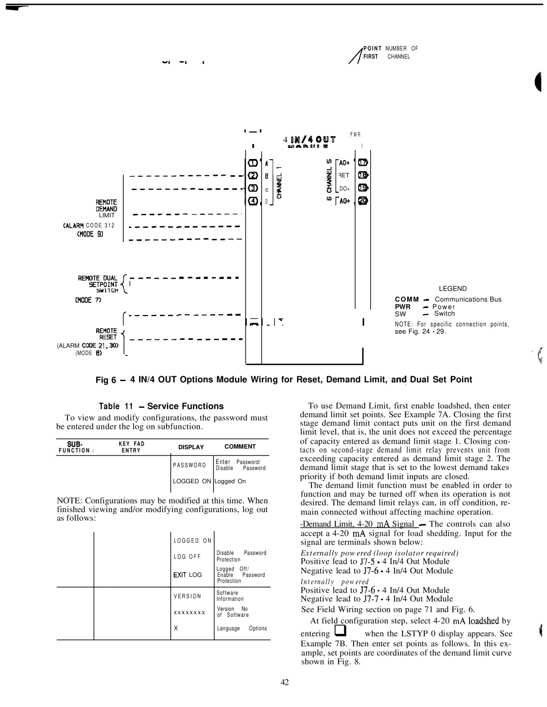
Fig 6 - 4 IN/4 OUT Options Module Wiring for Reset, Demand Limit, an! Dual Set Point

Table 11 - Service Functions

To view and modify configurations, the password must be entered under the log on subfunction.

SUB-

KEY FAD

DISPLAY

COMMENT

F U N C T I O N I

E N T R Y


PASSWORD

Enter

Password/


Disable

Password


LOGGED ON

Logged On


NOTE: Configurations may be modified at this time. When finished viewing and/or modifying configurations, log out as follows:


LOGGED

ON


LOG OFF


Disable

Password


Protection


Logged

Off/


EXIT LOG


Enable

Password


Protection


VERSION


Software


Information


xxxxxxxx

Version

No


of Software


X


Language

Options


To use Demand Limit, first enable loadshed, then enter demand limit set points. See Example 7A. Closing the first stage demand limit contact puts unit on the first demand limit level, that is, the unit does not exceed the percentage of capacity entered as demand limit stage 1. Closing con- tacts on second-stage demand limit relay prevents unit from exceeding capacity entered as demand limit stage 2. The demand limit stage that is set to the lowest demand takes priority if both demand limit inputs are closed.

The demand limit function must be enabled in order to function and may be turned off when its operation is not desired. The demand limit relays can, in off condition, re- main connected without affecting machine operation.

-Demand Limit, 4-20 mA Signal - The controls can also accept a 4-20 mA signal for load shedding. Input for the signal are terminals shown below:

Externally powered (loop isolator required)

Positive lead to 57-5 - 4 In/4 Out Module

Negative lead to 57-6 - 4 In/4 Out Module

Internally powered

Positive lead to J7-6 - 4 In/4 Out Module Negative lead to 57-7 - 4 In/4 Out Module

See Field Wiring section on page 71 and Fig. 6.

At field configuration step, select 4-20 mA loadshed by

entering q when the LSTYP 0 display appears. See Example 7B. Then enter set points as follows. In this ex- ample, set points are coordinates of the demand limit curve shown in Fig. 8.

42

Page 42
Image 42
Carrier 040-420 specifications Eke

040-420 specifications

The Carrier 040-420 is a highly regarded commercial HVAC unit specifically designed for efficient heating and cooling in medium- to large-sized buildings. Known for its reliability and advanced technology, this system is ideal for a variety of applications ranging from offices to industrial spaces.

One of the main features of the Carrier 040-420 is its energy efficiency. The unit utilizes advanced compressors and a high-efficiency heat exchanger, which work together to minimize energy consumption while maximizing performance. This is crucial in today’s energy-conscious environment, as businesses strive to reduce operational costs and their carbon footprint. The unit also boasts a high SEER (Seasonal Energy Efficiency Ratio) rating, making it an attractive option for those looking to lower their utility bills.

Equipped with advanced inverter-driven technology, the Carrier 040-420 allows for precise control of indoor climate conditions. This means that the system can adjust its output according to the actual cooling or heating demand of the space, resulting in enhanced comfort and reduced energy waste. The inverter technology also contributes to quieter operation, allowing for a more pleasant indoor environment.

Another feature that sets the Carrier 040-420 apart is its smart controls. The unit can be integrated with Carrier’s Building Automation Systems, enabling remote monitoring and management. This allows facility managers to optimize energy use and immediately respond to any performance issues. Additionally, the unit is compatible with various control interfaces, making it easy for users to adjust settings or schedule operations according to the building's occupancy patterns.

The robust design of the Carrier 040-420 ensures longevity and durability, even in harsh environmental conditions. Its weatherproof casing protects the internal components, enhancing the unit's performance and reliability over time. Maintenance is simplified with accessible design features, allowing technicians to conduct service checks and repairs without extensive downtime.

Overall, the Carrier 040-420 stands out as a modern HVAC solution that combines energy efficiency, advanced technologies, and user-friendly features. Its commitment to performance and sustainability makes it an ideal choice for businesses looking to enhance comfort while being mindful of their energy consumption. With its blend of innovation and reliability, the Carrier 040-420 continues to be a preferred option in the commercial HVAC market.