130 (50 Hz), 150-210, 225, 250, AND 280 UNITS (and associated modular units)

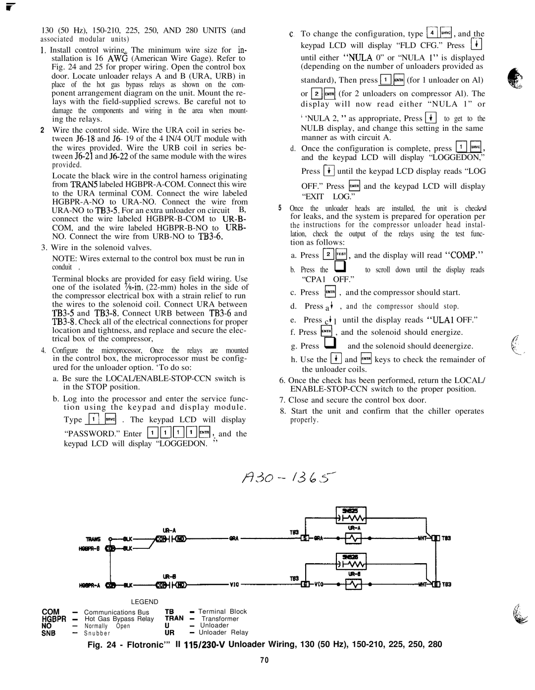
1.Install control wiring. The minimum wire size for in- stallation is 16 AWC (American Wire Gage). Refer to Fig. 24 and 25 for proper wiring. Open the control box door. Locate unloader relays A and B (URA, URB) in place of the hot gas bypass relays as shown on the com- ponent arrangement diagram on the unit. Mount the re- lays with the field-supplied screws. Be careful not to damage the components and wiring in the area when mount- ing the relays.

2Wire the control side. Wire the URA coil in series be- tween 56-18 and J6- 19 of the 4 IN/4 OUT module with the wires provided. Wire the URB coil in series be- tween J6-21 and J6-22 of the same module with the wires provided.

Locate the black wire in the control harness originating from TRANS labeled HGBPR-A-COM. Connect this wire to the URA terminal COM. Connect the wire labeled HGBPR-A-NO to URA-NO. Connect the wire from URA-NO to TB3-5. For an extra unloader on circuit B, connect the wire labeled HGBPR-B-COM to UR-B- COM, and the wire labeled HGBPR-B-NO to URB- NO. Connect the wire from URB-NO to TB3-6.

3.Wire in the solenoid valves.

NOTE: Wires external to the control box must be run in conduit +

Terminal blocks are provided for easy field wiring. Use one of the isolated ‘/s-in. (22-mm) holes in the side of the compressor electrical box with a strain relief to run the wires to the solenoid coil. Connect URA between TB3-5 and TB3-8. Connect URB between TB3-6 and TB3-8. Check all of the electrical connections for proper location and tightness, and replace and secure the elec- trical box of the compressor,

4.Configure the microprocessor, Once the relays are mounted in the control box, the microprocessor must be config- ured for the unloader option. ‘To do so:

a.Be sure the LOCAL/ENABLE-STOP-CCN switch is in the STOP position.

b.Log into the processor and enter the service func- t i o n u s i n g t h e k e y p a d a n d d i s p l a y m o d u l e .

Type r\ I;;;;E] . The keypad LCD will display

“PASSWORD.” Enter ~~1~~~~, and the keypad LCD will display “LOGGEDON. ”

C, To change the configuration, type 14 H, and the keypad LCD will display “FLD CFG.” Press m

until either “NULA 0” or “NULA I” is displayed (depending on the number of unloaders provided as

standard), Then press m H (for 1 unloader on Al)

or FiFi (for 2 unloaders on compressor Al). The d i s p l a y w i l l n o w r e a d e i t h e r “ N U L A 1 ” o r

‘ ‘NULA 2, ” as appropriate, Press I)I to get to the NULB display, and change this setting in the same manner as with circuit A.

d.Once the configuration is complete, press m Fi, and the keypad LCD will display “LOGGEDON,”

Press @ until the keypad LCD display reads “LOG

OFF.” Press H and the keypad LCD will display “EXIT LOG.”

5 Once the unloader heads are installed, the unit is checked. --for leaks, and the system is prepared for operation per the instructions for the compressor unloader head instal- lation, check the output of the relays using the test func- tion as follows:

a. Press T;1H, and the display will read “COMP.”

b. Press the q to scroll down until the display reads “CPA1 OFF.”

c. Press ENTR , and the compressor should start. 0

d.Press a + , and the compressor should stop.

e.Press c + l until the display reads “ULAl OFF.”

f.Press H , and the solenoid should energize.

g.Press q and the solenoid should deenergize.

h.Use the a and H keys to check the remainder of the unloader coils.

6.Once the check has been performed, return the LOCAL/ ENABLE-STOP-CCN switch to the proper position.

7.Close and secure the control box door.

8.Start the unit and confirm that the chiller operates properly.


LEGEND


COM

-

Communications Bus


- Terminal

Block

HGBPR

-

Hot Gas Bypass Relay

TLN

-

Transformer

KB

1

Normally Open


-

Unloader


Snubber

kl

- Unloader

Relay

Fig. 24 - Flotronic’” II 115/230-V Unloader Wiring, 130 (50 Hz), 150-210, 225, 250, 280

70

Page 70
Image 70
Carrier 040-420 specifications Hgbpr, Tln

040-420 specifications

The Carrier 040-420 is a highly regarded commercial HVAC unit specifically designed for efficient heating and cooling in medium- to large-sized buildings. Known for its reliability and advanced technology, this system is ideal for a variety of applications ranging from offices to industrial spaces.

One of the main features of the Carrier 040-420 is its energy efficiency. The unit utilizes advanced compressors and a high-efficiency heat exchanger, which work together to minimize energy consumption while maximizing performance. This is crucial in today’s energy-conscious environment, as businesses strive to reduce operational costs and their carbon footprint. The unit also boasts a high SEER (Seasonal Energy Efficiency Ratio) rating, making it an attractive option for those looking to lower their utility bills.

Equipped with advanced inverter-driven technology, the Carrier 040-420 allows for precise control of indoor climate conditions. This means that the system can adjust its output according to the actual cooling or heating demand of the space, resulting in enhanced comfort and reduced energy waste. The inverter technology also contributes to quieter operation, allowing for a more pleasant indoor environment.

Another feature that sets the Carrier 040-420 apart is its smart controls. The unit can be integrated with Carrier’s Building Automation Systems, enabling remote monitoring and management. This allows facility managers to optimize energy use and immediately respond to any performance issues. Additionally, the unit is compatible with various control interfaces, making it easy for users to adjust settings or schedule operations according to the building's occupancy patterns.

The robust design of the Carrier 040-420 ensures longevity and durability, even in harsh environmental conditions. Its weatherproof casing protects the internal components, enhancing the unit's performance and reliability over time. Maintenance is simplified with accessible design features, allowing technicians to conduct service checks and repairs without extensive downtime.

Overall, the Carrier 040-420 stands out as a modern HVAC solution that combines energy efficiency, advanced technologies, and user-friendly features. Its commitment to performance and sustainability makes it an ideal choice for businesses looking to enhance comfort while being mindful of their energy consumption. With its blend of innovation and reliability, the Carrier 040-420 continues to be a preferred option in the commercial HVAC market.