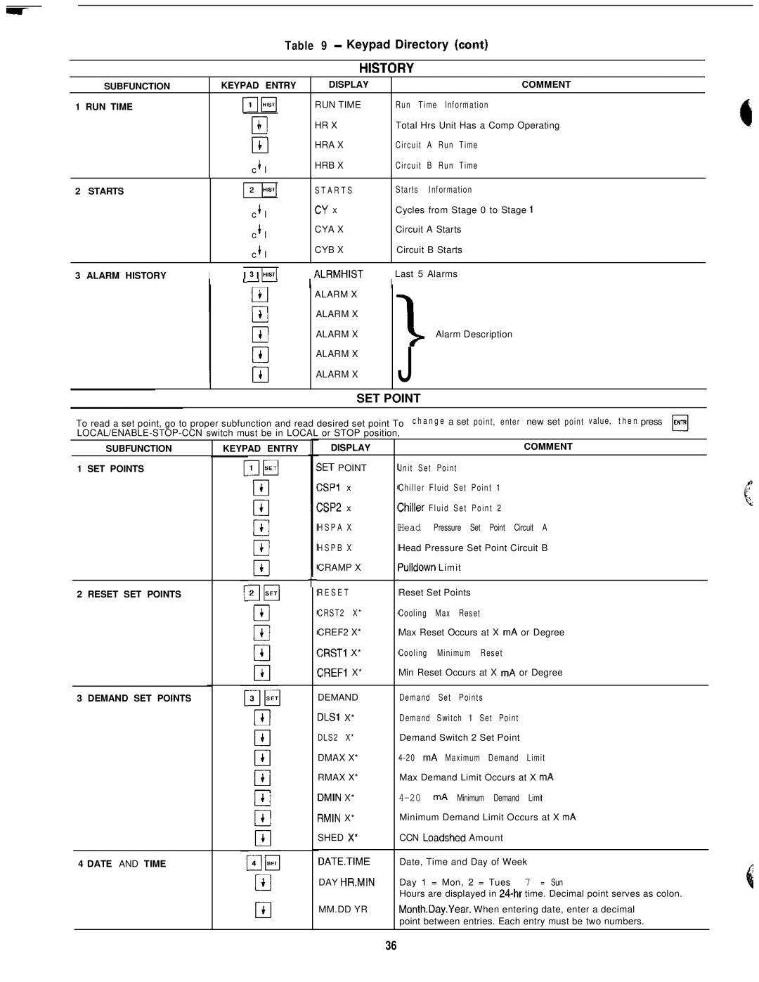
Table 9 - Keypad Directory (cant)


SUBFUNCTION


KEYPAD ENTRY


DISPLAY


COMMENT


1 RUN TIME


r;lm


RUN TIME


Run

Time lnformation


+


HR X


Total Hrs Unit Has a Comp Operating


0


4


HRA X


Circuit

A

Run

Time


cl


c b l


HRB X


Circuit

B

Run

Time


2

STARTS


1 2 1lHlST1


S T A R T S


Starts

Information


c + l


CY x


Cycles from Stage 0 to Stage 1


c + l


CYA X


Circuit A Starts


c + l


CYB X


Circuit B Starts


1ALRMHIST

1Last 5 Alarms


3

ALARM HISTORY

I


I 3 I lH4


ALARM X


ALARM X


ALARM X

>

Alarm Description


ALARM X


J


ALARM X


SET POINT


To read a set point, go to proper subfunction and read desired set point To

change a set point, enter new set point value, then press

ENTR


LOCAL/ENABLE-STOP-CCN switch must be in LOCAL or STOP position,


cl


SUBFUNCTION


KEYPAD ENTRY


DISPLAY


COMMENT


1 SET POINTS


SET POINT


Jnit

Set

Point


CSPl

x


Chiller Fluid Set Point 1


CSP2

x


Chiller

Fluid

Set Point 2


HSPA

X


Head


Pressure Set Point Circuit A


HSPB X


Head Pressure Set Point Circuit B


CRAMP X


Pulldown

Limit


t


2 RESET SET POINTS


RESET


Reset Set Points


CRST2

X*


Cooling

Max

Reset


CREF2 X*


Max Reset Occurs at X mA

or Degree


CRSTI

X*


Cooling

Minimum

Reset


CREFI X*


Min Reset Occurs at X mA

or Degree


3 DEMAND SET POINTS


DEMAND


Demand

Set

Points


DLSl

X*


Demand Switch 1 Set Point


DLS2

X*


Demand Switch 2 Set Point


DMAX X*


4-20

mA

Maximum

Demand

Limit


RMAX X*


Max Demand Limit Occurs at X mA


DMIN

X*


4-20


mA

Minimum Demand

Limit


RMIN

X*


Minimum Demand Limit Occurs at X mA


SHED X”


CCN Loadshed

Amount


4 DATE AND TIME


DATE.TIME


Date, Time and Day of Week


DAY HR.MIN


Day 1 = Mon, 2 = Tues

7 = Sun


Hours are displayed in 24-hr time. Decimal point serves as colon.


MM.DD YR


Month.Day.Year.

When entering date, enter a decimal


point between entries. Each entry must be two numbers.


36

Page 36
Image 36
Carrier 040-420 specifications Keypad Directory cant

040-420 specifications

The Carrier 040-420 is a highly regarded commercial HVAC unit specifically designed for efficient heating and cooling in medium- to large-sized buildings. Known for its reliability and advanced technology, this system is ideal for a variety of applications ranging from offices to industrial spaces.

One of the main features of the Carrier 040-420 is its energy efficiency. The unit utilizes advanced compressors and a high-efficiency heat exchanger, which work together to minimize energy consumption while maximizing performance. This is crucial in today’s energy-conscious environment, as businesses strive to reduce operational costs and their carbon footprint. The unit also boasts a high SEER (Seasonal Energy Efficiency Ratio) rating, making it an attractive option for those looking to lower their utility bills.

Equipped with advanced inverter-driven technology, the Carrier 040-420 allows for precise control of indoor climate conditions. This means that the system can adjust its output according to the actual cooling or heating demand of the space, resulting in enhanced comfort and reduced energy waste. The inverter technology also contributes to quieter operation, allowing for a more pleasant indoor environment.

Another feature that sets the Carrier 040-420 apart is its smart controls. The unit can be integrated with Carrier’s Building Automation Systems, enabling remote monitoring and management. This allows facility managers to optimize energy use and immediately respond to any performance issues. Additionally, the unit is compatible with various control interfaces, making it easy for users to adjust settings or schedule operations according to the building's occupancy patterns.

The robust design of the Carrier 040-420 ensures longevity and durability, even in harsh environmental conditions. Its weatherproof casing protects the internal components, enhancing the unit's performance and reliability over time. Maintenance is simplified with accessible design features, allowing technicians to conduct service checks and repairs without extensive downtime.

Overall, the Carrier 040-420 stands out as a modern HVAC solution that combines energy efficiency, advanced technologies, and user-friendly features. Its commitment to performance and sustainability makes it an ideal choice for businesses looking to enhance comfort while being mindful of their energy consumption. With its blend of innovation and reliability, the Carrier 040-420 continues to be a preferred option in the commercial HVAC market.